
Electromagnetic gun

A technology for an electromagnetic gun and a gun barrel, which is applied in the field of electromagnetic guns, can solve the problems that the electromagnetic gun is unfavorable to projectile launching, the current of the projectile coil is large, the synchronization technology is complex, and the like. Effect

Inactive Publication Date: 2015-10-07
HUBEI NORMAL UNIV
View PDF4 Cites 16 Cited by
  • Summary
  • Abstract
  • Description
  • Claims
  • Application Information

AI Technical Summary

Problems solved by technology

Projectile acceleration is often completed through multi-stage coil acceleration. During the acceleration process, the synchronization technology is relatively complicated, and the current of the projectile coil is very large. Overheating needs to be considered. The most important thing is that there will be a large induced electromotive force at the moment of acceleration, so The electromagnetic gun is very bad for the launch of the projectile

Method used


Image

  • Electromagnetic gun
  • Electromagnetic gun
  • Electromagnetic gun

Examples


Embodiment Construction

[0015] In order to make the object, technical solution and advantages of the present invention clearer, the present invention will be further described in detail below in conjunction with the accompanying drawings and embodiments. It should be understood that the specific embodiments described here are only used to explain the present invention, not to limit the present invention.

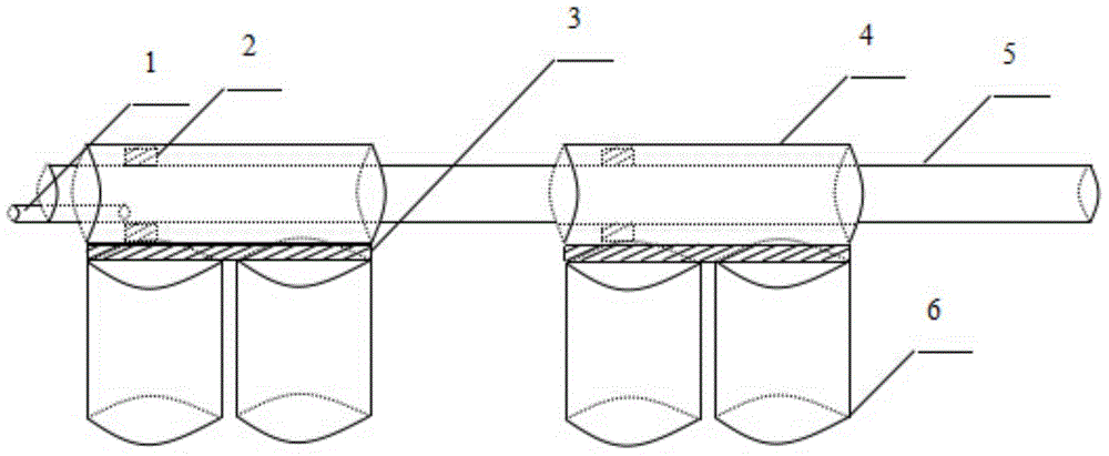
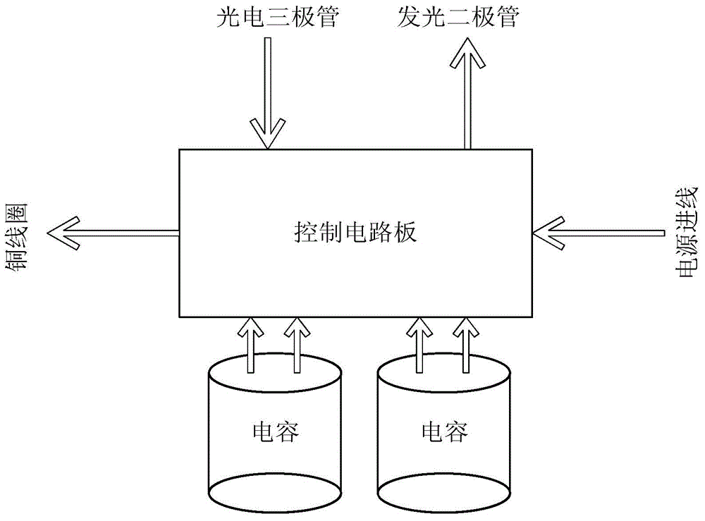
[0016] Such as Figure 1~4 As shown, among them, figure 1 It is the structural representation of electromagnetic gun of the present invention; figure 2 It is a structural schematic diagram of the circuit part in the electromagnetic gun of the present invention; image 3 It is the structural representation of the control circuit board in the electromagnetic gun of the present invention; Figure 4 It is the circuit structure diagram of the control circuit board in the electromagnetic gun of the present invention.

[0017] An electromagnetic gun is used to launch a projectile 1, including a gun b...


PUM


Abstract

The invention provides an electromagnetic gun. The gun tube is provided with multiple hole pairs in the vertical direction of the axis, and each hole pair is composed of two small holes arranged in the opposite side walls of the gun tube. Each copper coil, capacitors, each photoelectric triode and each light emitting diode are connected to one control circuit board; the photoelectric triode and the light emitting diode are respectively arranged in the two small holes of the hole pair of the gun tube; the copper coil wraps the hole pair of the gun tube; the control circuit board and the gun tube are erected on the capacitors; and the gun tube is internally provided with a bullet. The control circuit board is externally connected to a power supply so as to charge the capacitors. When the bullet moves to the hole pair, the control circuit board controls the capacitors to discharge electricity to the copper coil according to the change due to induction signal shielding, and the cooper coil can generate a strong magnetic field to drive the bullet to accelerate. According to the invention, a synchronization problem of multi-stage coils in an acceleration process is solved, the overheating of the coils can be reduced, and the electromagnetic gun is simple and compact in structure, is convenient to operate, is easy to adjust, is low in cost, and is high in stability and reliability.

Description

technical field [0001] The invention relates to a projectile launching device, in particular to an electromagnetic gun capable of accelerating the projectile through a multi-stage coil, so that the projectile has huge kinetic energy, and the speed of the projectile can easily break through the limit speed of ordinary artillery. Background technique [0002] At present, the electromagnetic guns launched by projectiles include coil guns, rail guns, and reconnection guns. Coilguns work by utilizing the interaction of magnetic fields between energized coils. The accelerating coil is fixed in the barrel, and when it is fed with an alternating current, the generated alternating magnetic field will generate an induced current in the projectile coil. The magnetic field of the induced current interacts with the magnetic field of the accelerating coil current to generate an electromagnetic field force, which accelerates the projectile and launches it. Railguns use the Ampere force o...

Claims


Application Information

Patent Timeline
Patent Type & Authority Applications(China)
IPC IPC(8): F41B6/00
Inventor 刘兴云鲁池梅
Owner HUBEI NORMAL UNIV
Learn More