Eureka AIR delivers breakthrough ideas for toughest innovation challenges, trusted by R&D personnel around the world.

Cross arm for electric power circuit

A power line and cross-arm technology, which is applied in the direction of building types, buildings, towers, etc., can solve problems such as troublesome operation, heavy loads, and unstable poles and towers, and achieve the effects of convenient adjustment process, highlighting substantive features, and reducing leakage accidents

Inactive Publication Date: 2015-10-07
STATE GRID SHANDONG ELECTRIC POWER +1
View PDF0 Cites 7 Cited by
  • Summary
  • Abstract
  • Description
  • Claims
  • Application Information

AI Technical Summary

Problems solved by technology

During installation, the cross arm is generally fixed on the pole tower by "U" type hoop or bolts. Because the pole tower is cylindrical, the contact surface between the cross arm and the pole tower is a straight line, and the contact area is small. The locking force of hoops or bolts cannot achieve reliable fixing of the cross arm and the pole tower; in addition, during use, the insulators and multiple hardware parts on the pole tower will increase the load of the cross arm on the one hand, and on the other hand, because the wire At the lower end of the insulator, the wire will generate a certain tension on the insulator. After long-term use, the iron cross-arm will be corroded, aged, deformed, etc., resulting in an unstable connection between the cross-arm and the tower. , so that the tower is not stable, and in severe cases, the cross arm will cause an electric leakage accident. At this time, maintenance personnel need to climb to the height of the tower, and then reinstall the cross arm after straightening. The operation is troublesome and the efficiency is low.

Method used


Image

  • Cross arm for electric power circuit
  • Cross arm for electric power circuit

Examples


Embodiment Construction

[0020] In order to clearly illustrate the technical features of the solution, the solution will be described below through a specific implementation mode combined with the accompanying drawings.

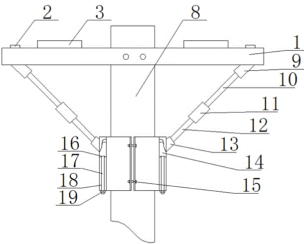
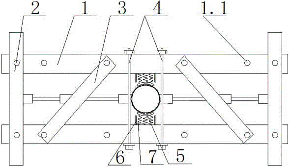
[0021] It can be seen from the accompanying drawings that a crossarm for power lines includes two crossarms 1 fixed on a pole tower 8, two longitudinal arms 2 are fixed at both ends of the two crossarms 1, and each crossarm 1 is provided with at least two threaded adjustment holes 1.1, and oblique arms 3 are symmetrically fixed between the threaded adjustment holes 1.1 of the two cross arms 1, and the oblique arms 3 can further increase the load bearing of the cross arm. According to the size of the installation space The position of the oblique arm 3 can be adjusted. In this way, the cross-arm bracket composed of the cross arm 1, the longitudinal arm 2 and the oblique arm 3 can bear the weight of the insulators, fittings, and lightning conductors.

[0022] The two transverse arms 1...


PUM


Abstract

The invention provides a cross arm for an electric power circuit. According to the technical scheme, the cross arm comprises two cross arm bodies fixed to a tower. The two ends of the two cross arm bodies are fixedly provided with two longitudinal arm bodies. The cross arm is characterized in that the inner sides of the two cross arm bodies are each provided with a first clamping ring matched with the tower, the cross arm further comprises second clamping rings matched with the tower and located below the cross arm bodies and the longitudinal arm bodies, the bottoms of the two longitudinal arm bodies are each hinged to a pull rod, and the other ends of the pull rods are in sliding connection with the second clamping rings. By adjusting the cross arm, the cross arm is in the balanced state and can be firmly fixed to the tower, maintenance is performed by workers conveniently, and the electric leakage accident caused by the cross arm is reduced.

Description

technical field [0001] The invention relates to a cross arm for power lines. Background technique [0002] The crossarm is an important part of the pole tower. Its function is to install insulators, fittings, and lightning conductors, and keep them at a certain safe distance according to regulations. During installation, the cross arm is generally fixed on the pole tower by "U" type hoop or bolts. Because the pole tower is cylindrical, the contact surface between the cross arm and the pole tower is a straight line, and the contact area is small. The locking force of hoops or bolts cannot achieve reliable fixing of the cross arm and the pole tower; in addition, during use, the insulators and multiple hardware parts on the pole tower will increase the load of the cross arm on the one hand, and on the other hand, because the wire At the lower end of the insulator, the wire will generate a certain tension on the insulator. After long-term use, the iron cross-arm will be corrode...

Claims


Application Information

Patent Timeline
IPC IPC(8): E04H12/24
Inventor 崔奎祥王长勇周磊韩峰刘功庆孙立山
Owner STATE GRID SHANDONG ELECTRIC POWER
Why Eureka
Eureka Blog
Learn More