Vacuum die

A vacuum mold and template technology, applied in the field of molds, can solve the problems of strain, uneven force of demoulding components, etc.

Inactive Publication Date: 2015-10-07
昆山—邦泰汽车零部件制造有限公司
View PDF3 Cites 5 Cited by
  • Summary
  • Abstract
  • Description
  • Claims
  • Application Information

AI Technical Summary

Problems solved by technology

In the existing injection mold, when demoulding, the force of the demoulding components is uneven, which will strain the relatively thin product position, and the existing technology has not solved such a problem

Method used


Image

  • Vacuum die
  • Vacuum die

Examples


Embodiment Construction

[0017] The present invention will be specifically introduced below in conjunction with the accompanying drawings and specific embodiments.

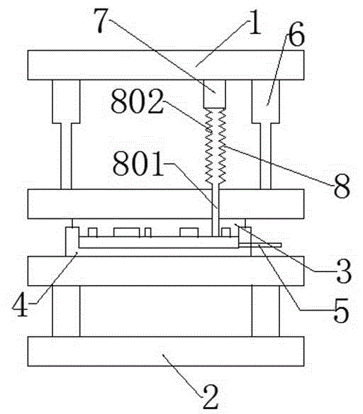
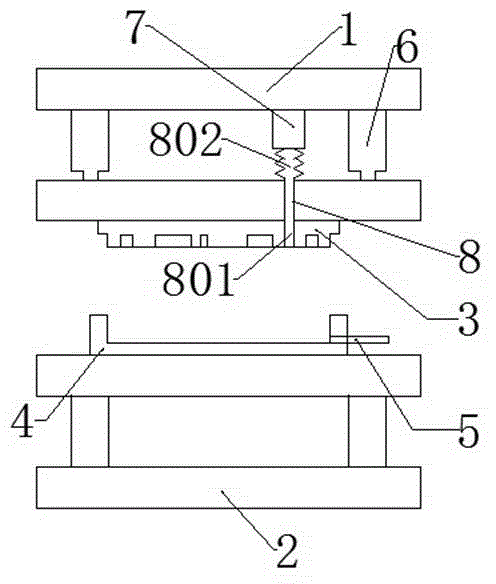
[0018] Vacuum mould, comprising: upper die base, lower die base 2, upper die base 3 under the upper die base, lower die base 4 fixed on lower die base 2, telescopic part connected between upper die base and upper die base 3 , As for the injection port 5 on the lower template 4, it is connected to the suction and blowing assembly of the upper template 3; Vacuum the molding tank before injection molding, which not only facilitates the entry of materials into the molding tank, but also prevents air bubbles or uneven product shapes due to air pressure when the product is molded. The molding groove is opened from the inside out, and the demoulding is clean and neat.

[0019] The suction blower assembly includes: as for the suction blower 7 on the upper template 3, the stretchable air duct 8 inserted into the upper template 3 and connected to ...


PUM


Abstract

The invention discloses a vacuum die. The vacuum die comprises an upper die base, a lower die base, an upper die plate arranged under the upper die base, a lower die plate fixed to the lower die base, a telescopic piece connected between the upper die base and the upper die plate, a sprue arranged on the lower die plate, and a wind sucking and blowing assembly connected to the upper die plate; and the wind sucking and blowing assembly comprises a sucking and blowing fan arranged on the upper die plate, and a stretchable wind tube inserted to the upper die plate and connected with the sucking and blowing fan. Vacuum is pumped from a molding tank before injection molding, so a material can conveniently enter the molding tank, and generation of bubbles generated in the molding process of a product or uneven product shape induced by gas pressure is avoided; air is injected to the molding tank during demolding, so the molding tank is opened outward by using an air pressure; complete and efficient demolding avoids pulling damages of the product, so the injection molding efficiency is improved, and the quality of the product is improved; and the wind tube of the sucking and blowing fan is provided with a telescopic fold tube, so the wind tube can change with the elongation or shortening of a telescopic rod.

Description

technical field [0001] A mold, especially an injection mold. Background technique [0002] Injection mold is a tool for producing plastic products; it is also a tool for giving plastic products complete structure and precise dimensions. Injection molding is a processing method used in the mass production of certain complex-shaped parts. Specifically, it refers to injecting the heated and melted material into the mold cavity by high pressure, and after cooling and solidifying, a molded product is obtained. In the existing injection mold, when demoulding, the force of the demoulding components is not uniform, which will strain the relatively thin product position, and the prior art has not yet solved such a problem. Contents of the invention [0003] In order to solve the deficiencies of the prior art, the purpose of the present invention is to provide a vacuum injection mold, which vacuumizes the molding tank before injection molding, which not only facilitates the entry ...

Claims


Application Information

Patent Timeline
Patent Type & Authority Applications(China)
IPC IPC(8): B29C45/26B29C45/43B29C45/57
CPCB29C45/43B29C45/26B29C45/57
Inventor 郑坚雄
Owner 昆山—邦泰汽车零部件制造有限公司
Why Eureka
Try Eureka