
Optimization method of automatic balance adjusting parameter of three-phase load

A technology of automatic balancing and parameter adjustment, applied in the direction of reducing the asymmetry of the polyphase network, eliminating/reducing the asymmetry of the polyphase network, etc., can solve the problem of reducing the output capacity of the transformer, increasing the line loss and the additional loss of the transformer, and increasing the reactive power. Loss and other problems, to achieve the effect of reducing output capacity, increasing additional loss, and increasing reactive power loss

Active Publication Date: 2015-09-30
广东天月德电力科技有限公司 +2
View PDF5 Cites 6 Cited by
  • Summary
  • Abstract
  • Description
  • Claims
  • Application Information

AI Technical Summary

Problems solved by technology

Since the connected three-phase loads are difficult to achieve equal balance, when the three-phase loads are unbalanced, it will inevitably lead to unequal currents in each phase, and the phase difference of the three-phase currents is not close to 120 degrees. When the voltage phase difference is large and the three-phase current is unbalanced
Unbalanced three-phase current leads to neutral line current not close to zero, increases reactive power loss, increases line loss and additional transformer loss, reduces transformer output capacity, and seriously low voltage of a certain phase or two phases at the end affects power quality. as a result of

Method used


Image

  • Optimization method of automatic balance adjusting parameter of three-phase load
  • Optimization method of automatic balance adjusting parameter of three-phase load
  • Optimization method of automatic balance adjusting parameter of three-phase load

Examples


Embodiment Construction

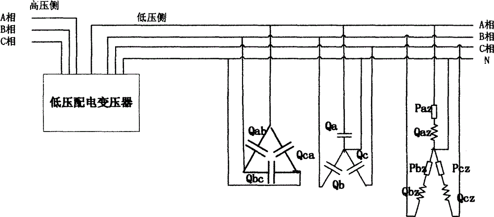
[0008] The purpose of the present invention is to generate reactive power compensation current between the phase line and the neutral line, generate active power transfer and reactive power adjustment current between the phase lines, resulting in the generation of the phase angle and amplitude of the current flowing into and out of the three-phase output line Change, the magnitude of the three-phase current tends to be equal, the phase difference of the three-phase current tends to be 120 degrees, and the phase difference between the three-phase current and the phase voltage tends to 0, so that the three-phase load reaches a balanced state.

[0009] The calculation method of the value of the capacitance or inductance element with different capacity inserted between the three-phase phase line and the neutral line of the present invention is based on the characteristics that the neutral line current can be expressed as the vector sum of the current of each phase, using the phase l...


PUM


Abstract

The invention relates to an optimization method of an automatic balance adjusting parameter of a three-phase load. The method is characterized in that capacitance or inductance elements with different capacities are connected between a three-phase line and a neutral line and between phase lines; current active powers and reactive powers of all phases are measured and then numerical values of the capacitance or inductance elements with different capacities are calculated, wherein the elements are connected between the three-phase line and the neutral line and between phase lines. In the prior art, when an unbalancing phenomenon occurs at a three-phase load, currents of all phases are not identical and the mutual deviation of the phases of the three-phase currents is not 120 degrees and phases of the three-phase currents and voltages are not identical, so that the unbalancing phenomenon occurs at the three-phase currents; the current of the neutral line is not zero due to the unbalancing phenomenon of the three-phase currents, so that the reactive losses are increased, the wire losses and additional losses of the transformer are increased, and the output capacity of the transformer is reduced; and the certain phase of voltage or the certain two phases of voltages at the tail end is or are low severely. Therefore, the electrical energy quality is affected. However, with the provided optimization method, the defects can be overcome.

Description

technical field [0001] The invention belongs to the technical field of electric power engineering, and in particular relates to an optimization method for three-phase load automatic balance adjustment parameters. Background technique [0002] At present, the power supply mode of the low-voltage distribution network mainly adopts the three-phase four-wire system, and most users adopt the load mode of connecting the phase line and the neutral line. Since the connected three-phase loads are difficult to achieve equal balance, when the three-phase loads are unbalanced, it will inevitably lead to unequal currents in each phase, and the phase difference of the three-phase currents is not close to 120 degrees. The situation where the three-phase current with a large voltage phase difference is unbalanced. Unbalanced three-phase current leads to neutral line current not close to zero, increases reactive power loss, increases line loss and additional transformer loss, reduces transf...

Claims


Application Information

Patent Timeline
Patent Type & Authority Applications(China)
IPC IPC(8): H02J3/26
CPCY02E40/50
Inventor 杨省苏崇文黄潮灿李卓坚陈小倩姚普粮龙光成李强纪湛黄种川麦汉辉梁玉劲梁海张华丽陈荆伟黄洁斯李国伟杨淞搏
Owner 广东天月德电力科技有限公司
Learn More