
Efficient pressure buildup device for die casting machine

A die-casting machine, high-efficiency technology, used in fluid pressure actuation devices, mechanical equipment, fluid pressure converters, etc., which can solve problems such as long time and influence on pressure build-up time

Active Publication Date: 2015-09-30
广东联升精密机械制造有限公司
View PDF7 Cites 8 Cited by
  • Summary
  • Abstract
  • Description
  • Claims
  • Application Information

AI Technical Summary

Problems solved by technology

[0003] The injection action sequence is generally: the first slow speed - the second slow speed - fast - pressurized, because there is an action connection between the fast and pressurized action, that is, the fast end signal is transmitted to the PLC - the PLC responds to let The electromagnet of the oil valve is energized—the electromagnet pushes the spool of the oil valve—the spool of the cartridge valve is opened—the booster cylinder is pushed out. The time is too long, which affects the pressure building time
[0004] The shorter the pressure build-up time is generally required, the better, but the 30ms-100ms pressure build-up time achieved by the existing technology still cannot meet the needs of modern production, and there is still room for improvement. Therefore, in order to improve the performance of the die-casting machine, it is necessary to make further improvements

Method used


Image

  • Efficient pressure buildup device for die casting machine
  • Efficient pressure buildup device for die casting machine
  • Efficient pressure buildup device for die casting machine

Examples


Embodiment Construction

[0015] The present invention will be further described below in conjunction with the accompanying drawings and embodiments.

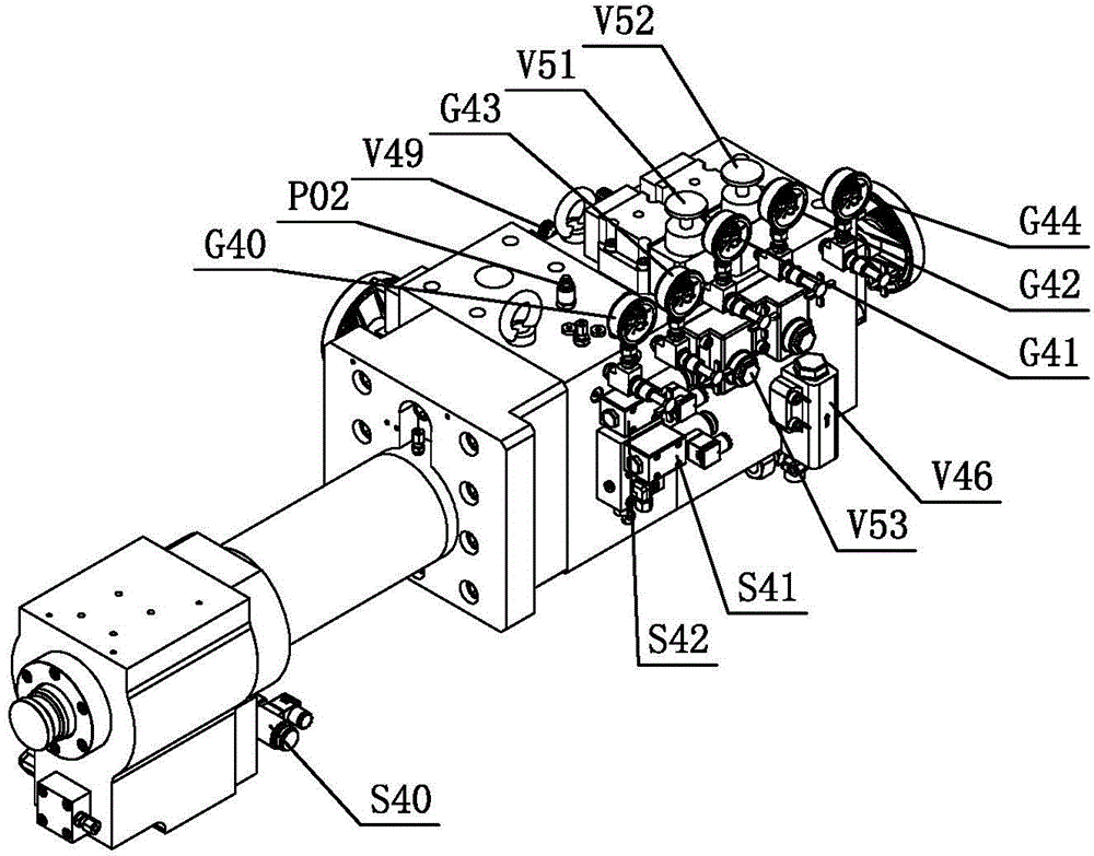
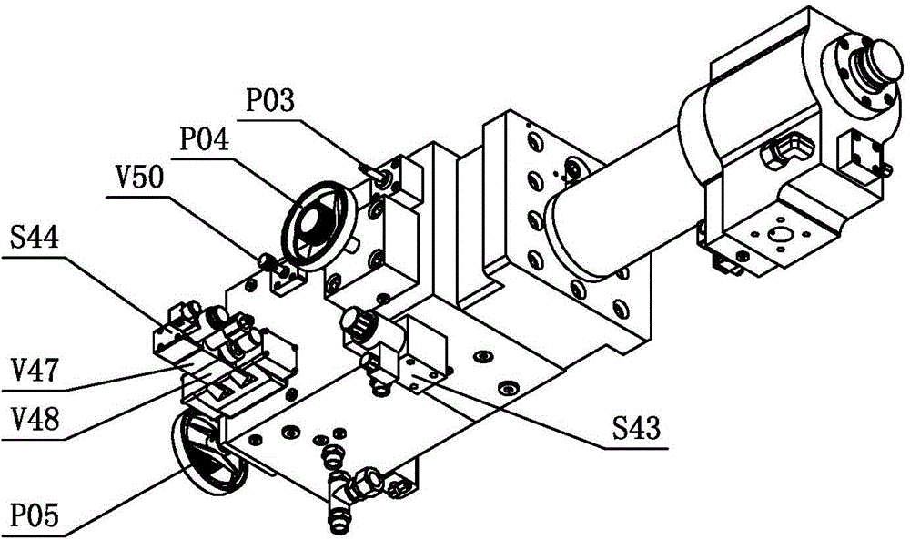
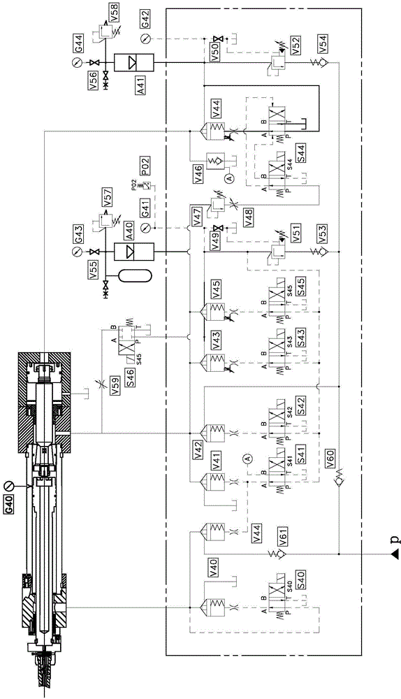
[0016] see Figure 1-Figure 3 , the high-efficiency pressure building device for die-casting machines includes a pressurized oil cylinder and an injection oil cylinder, and also includes a fourth cartridge valve V43 and a fourth electromagnetic reversing valve S43 connected in series on the oil circuit, and a first cartridge connected in series The valve V40 and the first electromagnetic reversing valve S40, the third cartridge valve V42 and the third electromagnetic reversing valve S42 connected in series, the sixth cartridge valve V45 and the sixth electromagnetic reversing valve S45 connected in series, and the interconnected The fifth cartridge valve V44 and the throttling screw V61, the first accumulator A40 connected in series, the first pressure reducing valve V51 and the first one-way valve V53, the overflow valve V47 connected to each other and...


PUM


Abstract

An efficient pressure buildup device for a die casting machine comprises a boost oil cylinder and an injection oil cylinder, and is characterized in that an oil way comprises a fourth cartridge valve and a fourth electromagnetic directional valve which are mutually connected in series, a first cartridge valve and a first electromagnetic directional valve which are mutually connected in series, a third cartridge valve and a third electromagnetic directional valve which are mutually connected in series, a sixth cartridge valve and a sixth electromagnetic directional valve which are mutually connected in series, a fifth cartridge valve and a throttling screw which are mutually connected, a first energy accumulator, a first pressure reducing valve and a first one-way valve which are mutually connected in series, an overflow valve and a fifth electromagnetic directional valve which are mutually connected, as well as a second energy accumulator, a second pressure reducing valve and a second one-way valve which are mutually connected in series. According to the structure, power is gained while electromagnets are boosted during rapidly acting, signal receiving and action command transmitting time of a PLC (programmable logic controller) is saved, and only two processes including opening of cartridge valve cores and pushing-out of the boost oil cylinder are reserved, so that the pressure buildup time is shortened. The efficient pressure buildup device for the die casting machine has the characteristics of simple and reasonable structure, short pressure buildup time and low cost.

Description

technical field [0001] The invention relates to a pressure building device, in particular to an efficient pressure building device used in a die casting machine. Background technique [0002] The pressure building time is an important performance parameter of the injection system of the die-casting machine. The shorter the time for the pressure-building process of the die-casting machine, the more advanced the performance of the injection system of the die-casting machine. In the die-casting process, the shorter the pressure build-up time used, the more beneficial it is to improve the quality of the casting. The shortest pressure build-up time of the die-casting machine is an important basis for evaluating the performance and technical level of the injection system of the die-casting machine. At present, the die-casting machine manufacturer can achieve the shortest The pressure building time is about 30ms ~ 100ms. [0003] The injection action sequence is generally: the fir...

Claims


Application Information

Patent Timeline
IPC IPC(8): F15B1/02F15B13/06F15B3/00B22D17/20
CPCB22D17/2015F15B1/02F15B3/00F15B13/06
Inventor 刘会日彭新上周红剑
Owner 广东联升精密机械制造有限公司
Learn More