
steam turbine with resonant cavity

A technology of steam turbines, resonant chambers, applied in the direction of supporting elements of blades, machines/engines, engine functions, etc.

Active Publication Date: 2019-03-08
GENERAL ELECTRIC TECH GMBH
View PDF10 Cites 0 Cited by
  • Summary
  • Abstract
  • Description
  • Claims
  • Application Information

AI Technical Summary

Problems solved by technology

[0003] While various methods of damping vibration are known, including magnetic coupling as discussed in U.S. Patent No. 4,722,668, fluid jetting as discussed in U.S. Patent Application No. 2013 / 0280050 A1, and vane tuning as discussed in U.S. Patent No. 4,878,810 A, there is still Alternative vibration isolation methods required

Method used


Image

  • steam turbine with resonant cavity
  • steam turbine with resonant cavity

Examples


Embodiment Construction

[0028] Exemplary embodiments of the present disclosure are now described with reference to the drawings, wherein like reference numerals are used to represent like elements throughout. In the following description, for purposes of explanation, numerous specific details are set forth in order to provide a thorough understanding of the disclosure. However, the present disclosure may be practiced without these specific details and the disclosure is not limited to the exemplary embodiments disclosed herein.

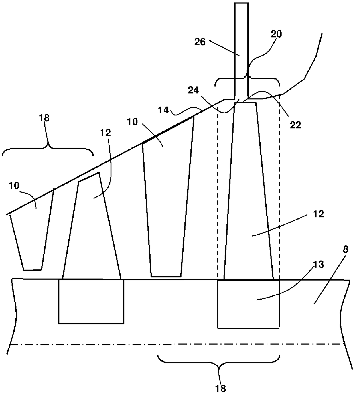
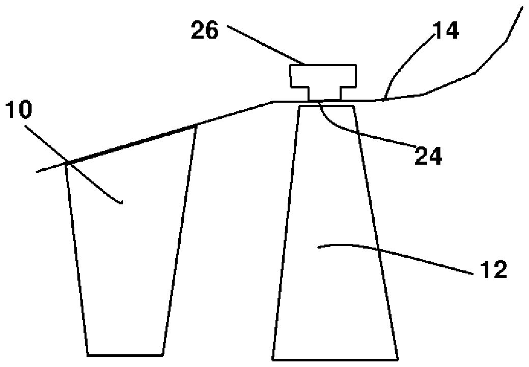
[0029] In the exemplary embodiment, as figure 1 As shown in , comprises a steam turbine having: a rotor 8; a circumferentially distributed row of rotating blades 12 extending radially from a root 13 attached to the rotor 8 to a tip portion 22; and an outer ring 14 which The row of blades 12 is circumferentially enclosed to form an outer ring 14 . The stages 18 of the steam turbine are defined as a combination of stationary vane rows 10 and rotating blade rows 12 . Such a s...


PUM


Abstract

The present invention relates to a steam turbine with a resonant cavity. In particular, it relates to a steam turbine having a resonant cavity (26) in an outer annulus (14) opposite a row of rotating blades (12). The resonant cavity (26) provides passive resonance so that the excitation is at a frequency away from the natural frequency of the blade (12).

Description

technical field [0001] The present disclosure relates generally to steam turbines, and more particularly, to systems for reducing vibration of steam turbine blades. Background technique [0002] Turbine blades, due to their complex design, may be subject to vibrations at frequencies corresponding to the blade's natural frequencies, called modes. Each mode is associated with a different type of vibration, such as along the axis of rotation of the turbine, perpendicular to the axis of rotation of the turbine, and so on. To prevent excessive vibration of the blades about their normal position, common design practice dictates that the blades be constructed such that those modes lie between harmonics of the operating frequency of the steam turbine. However, manufacturing tolerances, variations in the attachment of the blades to the rotor, variations in the geometry of the blades due to erosion, and variations in the operating frequency of the turbine, among others, result in mod...

Claims


Application Information

Patent Timeline
Patent Type & Authority Patents(China)
IPC IPC(8): F01D25/06
CPCF01D25/04F05D2260/963F05D2220/31F01D5/10F01D5/30F01D5/06F05D2240/24
Inventor T.S.赖斯
Owner GENERAL ELECTRIC TECH GMBH
Learn More