
Device for Improving Bearing Performance of Steel Arch Frame in Large-Section Tunnel with Expansion-Contraction Soil

A technology of expanding and shrinking soil and large cross-section, applied in tunnels, tunnel linings, shaft equipment, etc., can solve the problems of short action time, general effect, and the large arch foot structure cannot meet the free change, and achieves easy quality and construction process. simple effect

Inactive Publication Date: 2017-04-05
SHANDONG UNIV
View PDF5 Cites 0 Cited by
  • Summary
  • Abstract
  • Description
  • Claims
  • Application Information

AI Technical Summary

Problems solved by technology

[0004] 1. Adopt large arch foot structure: Although the support structure of large arch foot can reduce the earth pressure on the tunnel face, reduce the vault and surface settlement, and improve the self-stabilization ability of the surrounding rock, but for the expansive soil itself Due to the characteristics of water absorption expansion and water loss contraction, the large arch foot structure cannot satisfy the free change with the deformation of the surrounding rock, resulting in uneven settlement deformation of the tunnel support structure
[0005] 2. Adopt flexible support structure: Although the deformability of the tunnel support structure can be realized, its reinforcement range is relatively small, and the action time is short, the ability to improve the self-stabilization of the tunnel surrounding rock is limited, and the effect of controlling the surface settlement is general. The reinforcement range cannot be effectively formed, thereby reducing reliability

Method used


Image

  • Device for Improving Bearing Performance of Steel Arch Frame in Large-Section Tunnel with Expansion-Contraction Soil
  • Device for Improving Bearing Performance of Steel Arch Frame in Large-Section Tunnel with Expansion-Contraction Soil
  • Device for Improving Bearing Performance of Steel Arch Frame in Large-Section Tunnel with Expansion-Contraction Soil

Examples


Embodiment Construction

[0034] Below in conjunction with accompanying drawing and embodiment the patent of the present invention is described further.

[0035] It should be understood that the focus of this article is on the improvement proposed for the arch foot support structure of the steel arch, and the corresponding structure of the steel arch involved can be easily ascertained by those skilled in the art based on the relevant technologies in the field .

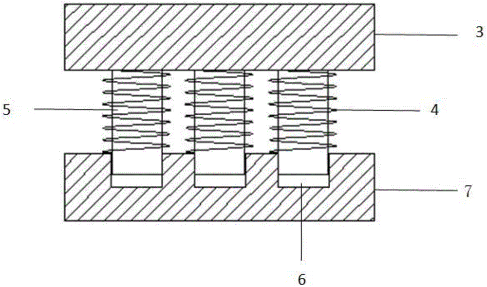
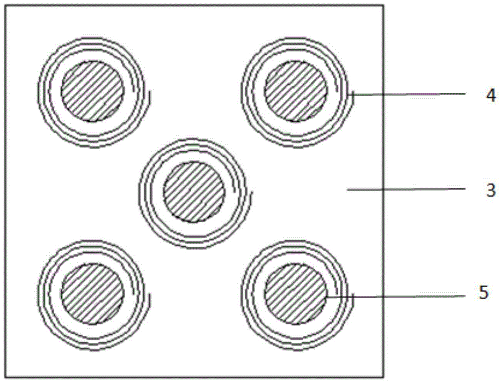
[0036] Such as figure 1 , figure 2 , image 3 , Figure 4 , Figure 5 As shown, a device for improving the load-bearing performance of the steel arch frame of a large-section tunnel in expansion-contraction soil includes a large arch foot 2 arranged at the bottom of the steel arch frame 1, wherein the large arch foot 2 is composed of an upper steel plate 3 and a lower steel plate 7. Composed of high-strength spiral steel bar 4, rigid support 5 and support slot 6. Arrange high-strength spiral steel bars 4 and rigid supports 5 at the four...


PUM

PropertyMeasurementUnit
thicknessaaaaaaaaaa

Abstract

The invention discloses a device for improving the bearing performance of a steel arch of a dilative soil large-section tunnel. The device comprises an arched support. High-strength round spiral steel bars and rigid supporting bases are arranged at large arch feet at the bottom of the arched support, each large arch foot comprises an upper-layer steel plate and a lower-layer steel plate connected with the upper-layer steel plate through five high-strength round spiral steel bars in a plum pile mode, and the rigid supporting bases penetrate through the high-strength spiral steel bars; five supporting base insertion grooves are formed in each lower-layer steel plate, and the supporting base insertion grooves are used for fixing the supporting bases so as to guarantee the overall stability of the steel arch. The device can relieve the settlement deformation of surrounding rock at the initial stage of excavation of the dilative soil tunnel, improve the self-stabilization capacity of the tunnel effectively and lastingly, form a multifunctional surrounding rock reinforcement area and guarantee the safety of tunnel constructors and protect equipment.

Description

technical field [0001] The patent of the invention relates to the technical field of geotechnical engineering, in particular to a device for improving the load-bearing performance of the steel arch frame of a large-section tunnel with expansion-contraction soil. Background technique [0002] In expansive soil areas, when constructing large-section tunnels such as railways and highways, the expansive soil itself has the characteristics of water absorption and shrinkage, which can easily cause cracks on the tunnel surface and excessive deformation of the surrounding rock, resulting in collapse. Geological disasters such as mud gushing occur, thereby endangering the life safety of construction workers and damaging production equipment. According to the monitoring results of the surrounding rock deformation of many large-section tunnels on railways and highways, it can be known that the deformation of the surrounding rock of expansion-contraction soil tunnels has the characteris...

Claims


Application Information

Patent Timeline
Patent Type & Authority Patents(China)
IPC IPC(8): E21D11/18
Inventor 武科张文吴昊天
Owner SHANDONG UNIV
Learn More