
Liquefiable sandy soil structure

A technology for sandy soil and sandy soil layer, which is applied in the direction of infrastructure engineering, soil protection, construction, etc., can solve the problems of unreachable usability, and achieve the effects of improving anti-liquefaction ability, reducing settlement phenomenon, and good drainage

Inactive Publication Date: 2015-09-30
CHENGDU XUNDE SCI & TECH
View PDF0 Cites 0 Cited by
  • Summary
  • Abstract
  • Description
  • Claims
  • Application Information

AI Technical Summary

Problems solved by technology

[0002] In hydropower projects, it is often necessary to build dams or construct hydraulic structures on the river bed cover layer. The cause and composition of the river bed cover layer are usually relatively complicated. In hydropower projects, the foundation is often buried deep and thick. Thick and widely distributed liquefiable sand layers, especially when the foundation of the water retaining dam is such a situation, in order to meet the stability requirements of the dam, it is necessary to treat the sand layer of the dam foundation. This kind of anti-liquefaction effect is good, easy to construct and relatively economical anti-liquefaction treatment technology for foundation sand layer, but only relying on vibrating gravel piles cannot achieve better usability, and it needs to be combined with other components to better achieve Effect

Method used


Image

  • Liquefiable sandy soil structure

Examples


Embodiment Construction

[0013] The present invention will now be described in further detail in conjunction with the accompanying drawings, which are simplified schematic diagrams, only schematically illustrating the basic structure of the present invention, and therefore only show the configurations related to the present invention.

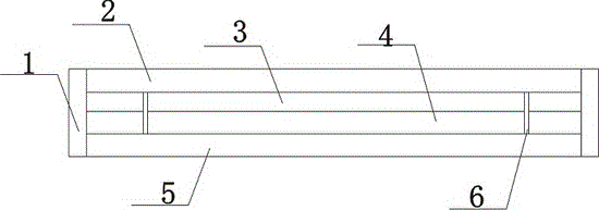
[0014] Such as figure 1 The preferred embodiment of the liquefied sandy soil structure of the present invention shown includes a liquefiable sandy soil layer 2, the lower surface of the liquefiable sandy soil layer 2 is provided with a concrete sandstone layer 3, and the thickness of the concrete sandstone layer 3 is smaller than that of the liquefiable sandy soil layer 2. Thickness, non-woven fabric is laid between the liquefiable sand layer 2 and the concrete sand layer 3, the lower surface of the concrete sand layer 3 is provided with an anti-leakage sand layer 4, and the anti-leakage layer 4 is connected with the concrete sand layer The layers 3 are connected by st...


PUM


Abstract

The invention discloses a liquefiable sandy soil structure. The liquefiable sandy soil structure comprises a liquefiable sandy soil layer. The lower surface of the liquefiable sandy soil layer is provided with a concrete gravel layer. The thickness of the concrete gravel layer is smaller than that of the liquefiable sandy soil layer. Non-woven cloth is laid between the liquefiable sandy soil layer and the concrete gravel layer. The lower surface of the concrete gravel layer is provided with an anti-seep gravel layer. The anti-seep gravel layer is connected with the concrete gravel layer through steel pipe piles. The steel pipe piles are fixed to the anti-seep gravel layer and the concrete gravel layer. The lower surface of the anti-seep gravel layer is provided with a broken stone hardcore. Reinforcing rods are embedded between the broken stone hardcore and the anti-seep gravel layer. The liquefiable sandy soil structure further comprises vibro-replacement stone columns. The liquefiable sandy soil structure has very high bearing capacity, very high permeable capacity, capable of effectively reducing sedimentation generated after construction as well as improving the liquefying resistance capacity of a foundation and capable of playing a role in water drainage better so that next construction process can be better conducted, and construction efficiency is improved greatly.

Description

technical field [0001] The invention relates to a sandy soil structure, in particular to a liquefied sandy soil structure. Background technique [0002] In hydropower projects, it is often necessary to build dams or construct hydraulic structures on the river bed cover layer. The cause and composition of the river bed cover layer are usually relatively complicated. In hydropower projects, the foundation is often buried deep and thick. Thick and widely distributed liquefiable sand layers, especially when the foundation of the water retaining dam is such a situation, in order to meet the stability requirements of the dam, it is necessary to treat the sand layer of the dam foundation. This kind of anti-liquefaction effect is good, easy to construct and relatively economical anti-liquefaction treatment technology for foundation sand layer, but only relying on vibrating gravel piles cannot achieve better usability, and it needs to be combined with other components to better achie...

Claims


Application Information

Patent Timeline
Patent Type & Authority Applications(China)
IPC IPC(8): E02D27/40E02D3/08
Inventor 龚素华
Owner CHENGDU XUNDE SCI & TECH
Learn More