Hole collapse preventive trenching construction method of underground diaphragm wall

An underground continuous wall and grooved construction technology, which is applied in excavation, infrastructure engineering, construction, etc., can solve problems such as ground subsidence, increase in concrete volume, affecting the normal use of surrounding buildings and municipal facilities, and reduce engineering accidents. , Improve the effect of construction quality

Inactive Publication Date: 2015-09-30
THE THIRD CONSTR CO LTD OF YNJG
View PDF7 Cites 4 Cited by
  • Summary
  • Abstract
  • Description
  • Claims
  • Application Information

AI Technical Summary

Problems solved by technology

If there are a large number of collapsed holes in the tank wall, the amount of mud and the amount of concrete poured into the underground diaphragm wall will increase greatly, and the ground will subside, which will affect the normal use of surrounding buildings and municipal facilities, and even affect the safety of life and property.

Method used


Image

  • Hole collapse preventive trenching construction method of underground diaphragm wall
  • Hole collapse preventive trenching construction method of underground diaphragm wall
  • Hole collapse preventive trenching construction method of underground diaphragm wall

Examples


Embodiment 1

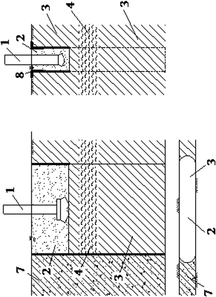
[0022] Example 1 : The first step: such as figure 1 As shown, measure the positioning, determine the excavation position of the guide wall 8, make the guide wall 8, prepare the mud 2, and prepare the mud circulation system, the trough forming machine is in place, the set deviation requirements are reviewed, and the trough forming machine is started. Troughing machine grab 1 starts to take soil to form a trough;

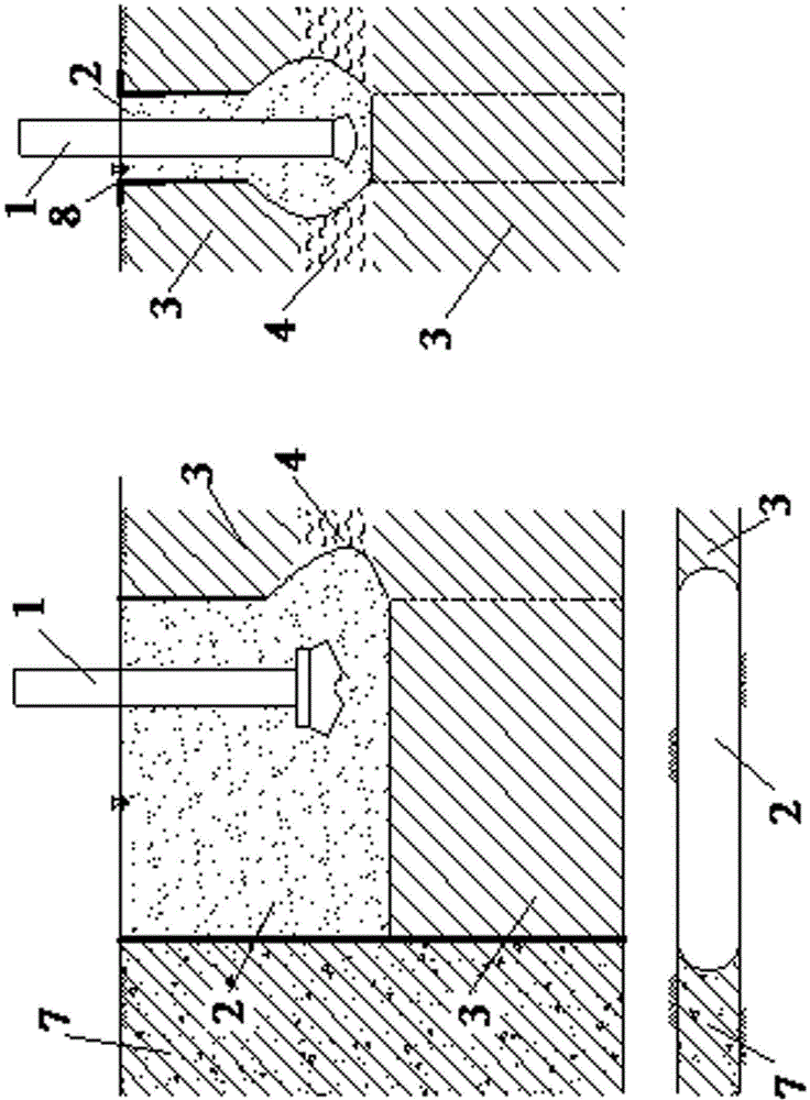
[0023] The second step: such as figure 2 As shown, the trough forming machine excavates soil in the soil layer 3 to form a trough, and maintains the mud water level in the trough section during trough formation to ensure that the hydrostatic pressure generated by the mud meets the design requirements. When the trough reaches the weak soil layer 4, if the trough wall collapses, such as a large amount of mud leakage in the trough, the mud level will drop significantly; a lot of foam or agitation appears in the mud 2; the amount of mud discharged is significantly larger th...

Embodiment 2

[0027] Example 2 : The first step: such as figure 1 As shown, measure the positioning, determine the excavation position of the guide wall 8, make the guide wall 8, prepare the mud 2, and prepare the mud circulation system, the trough forming machine is in place, the set deviation requirements are reviewed, and the trough forming machine is started. Troughing machine grab 1 starts to take soil to form a trough;

[0028] The second part: such as figure 2 As shown, the trough forming machine excavates soil in the soil layer 3 to form a trough, and maintains the mud water level in the trough section during trough formation to ensure that the hydrostatic pressure generated by the mud meets the design requirements. When the trough reaches the weak soil layer 4, if the trough wall collapses, such as a large amount of mud leakage in the trough, the mud level will drop significantly; a lot of foam or agitation appears in the mud 2; the amount of mud discharged is significantly larger t...


PUM


Abstract

The invention belongs to the field of building foundation pit engineering and discloses a hole collapse preventive trenching construction method of an underground diaphragm wall. A construction is composed of a grab bucket (1) of a trenching machine, retaining wall slurry (2), a soil layer (3), a soft soil layer (4), a conduit (5), cemented soil (6), an underground diaphragm wall (7) constructed, and guide walls (8). The underground diaphragm wall easily suffers hole collapse during trenching construction; to solve the problem, a trench of the underground diaphragm wall can be filled with the cemented soil reaching 1 to 2 m above the trench hole collapse part, and soft retaining walls form after settling and compacting; after the cemented soil has stable quality and has certain strength, trenching construction continues, and the soft retaining walls made up of the cemented soil function in retaining jointly with the slurry so as to prevent hole collapse. The environment with the soft soil layer is improved through the cemented soil, the soft retaining walls are formed and finish retaining jointly with the slurry, the problem that lateral supporting force of the slurry is poor is effectively solved, the soft soil layer of high flow plasticity is protected from hole collapse, smoothness of trenching is ensured, and trenching quality is improved.

Description

technical field [0001] The invention relates to a trench-forming construction method for an underground diaphragm wall, in particular to a trench-forming construction method for an underground diaphragm wall for anti-collapse holes, and belongs to the field of building foundation pit engineering. Background technique [0002] In recent years, with the progress of urban construction, the degree of development of underground space has increased unprecedentedly, the excavation depth and width of foundation pits have become larger and larger, and the geological conditions faced have become worse and worse. In addition, the surrounding dense buildings And the adjacent municipal facilities have brought certain difficulties to the design and construction of the support structure of the foundation pit. At present, for foundation pits of high safety level with complex surrounding environment, poor geological conditions, and large excavation depth, the supporting structure usually ado...

Claims


Application Information

Patent Timeline
Patent Type & Authority Applications(China)
IPC IPC(8): E02D17/06E02D17/08
Inventor 杨少真王长录殷华富彭云许艳苗谭沧海邵维福李文艳徐春荣叶正凯李杰源
Owner THE THIRD CONSTR CO LTD OF YNJG
Why Eureka
Try Eureka