
Adaptive large modulation bandwidth I/Q modulation error digital compensation method and adaptive large modulation bandwidth I/Q modulation error digital compensation system

An error compensation and error compensator technology, applied in the field of adaptive large modulation bandwidth I/Q modulation error digital compensation method and system, can solve the limitation of calibration accuracy, high resource and time consumption requirements, and large difference in calibration state, etc. problem, to achieve high-precision compensation correction, avoid traversal search, break through the effect of bandwidth constraints

Active Publication Date: 2015-09-23
THE 41ST INST OF CHINA ELECTRONICS TECH GRP
View PDF3 Cites 17 Cited by
  • Summary
  • Abstract
  • Description
  • Claims
  • Application Information

AI Technical Summary

Problems solved by technology

[0013] 1. The above-mentioned existing vector modulation error analog calibration compensation method requires a series of complex analog circuits, including: calibration source, attenuator, bias voltage generation circuit and phase shifter, etc. The engineering implementation is difficult, and the calibration accuracy is limited by the analog device itself. precision limit
[0014] 2. The compensation parameter list established through the calibration process is obtained under the separate excitation of the calibration source. The actual baseband signal under normal working conditions is quite different from the calibration state, and only approximate calibration can be achieved.
[0015] 3. Due to the limitation of the performance of the analog device itself, the analog calibration method can only realize the calibration compensation of the vector modulation error with a narrow modulation bandwidth due to the limitation of the performance of the analog device itself.
Situations where a large modulation bandwidth of the order of GHz cannot be met
[0016] 4. The simulation calibration method is based on the preset compensation parameter list, which requires traversal search, which requires high resource and time consumption. At the same time, it is limited by the step value of the list parameters, which has a significant impact on the calibration accuracy

Method used


Image

  • Adaptive large modulation bandwidth I/Q modulation error digital compensation method and adaptive large modulation bandwidth I/Q modulation error digital compensation system
  • Adaptive large modulation bandwidth I/Q modulation error digital compensation method and adaptive large modulation bandwidth I/Q modulation error digital compensation system
  • Adaptive large modulation bandwidth I/Q modulation error digital compensation method and adaptive large modulation bandwidth I/Q modulation error digital compensation system

Examples


Embodiment 1

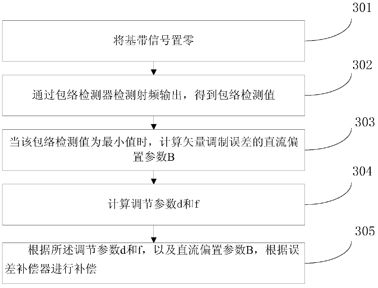
[0047] image 3 It is a flow chart of a vector modulation error compensation method for independent frequency points according to Embodiment 1 of the present invention. Such as image 3 shown, including the following steps:

[0048] Step 301, the baseband signal V o Zero;

[0049] Step 302, the radio frequency output is detected by the envelope detector to obtain the envelope detection value V e ;

[0050] Step 303, when the envelope detection value V e When is the minimum value, calculate the DC bias parameter B of the vector modulation error;

[0051] Step 304, calculating adjustment parameters d and f;

[0052] Put the input volume V o Take the following values ​​respectively:

[0053] V 1 o = [ 0 , Λ ] T , V 2 o = ...

Embodiment 2

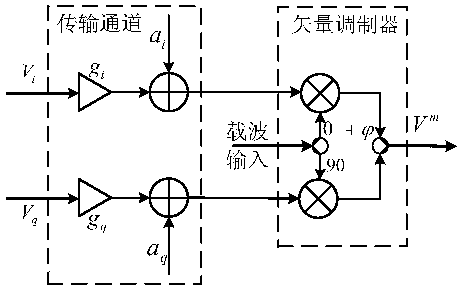
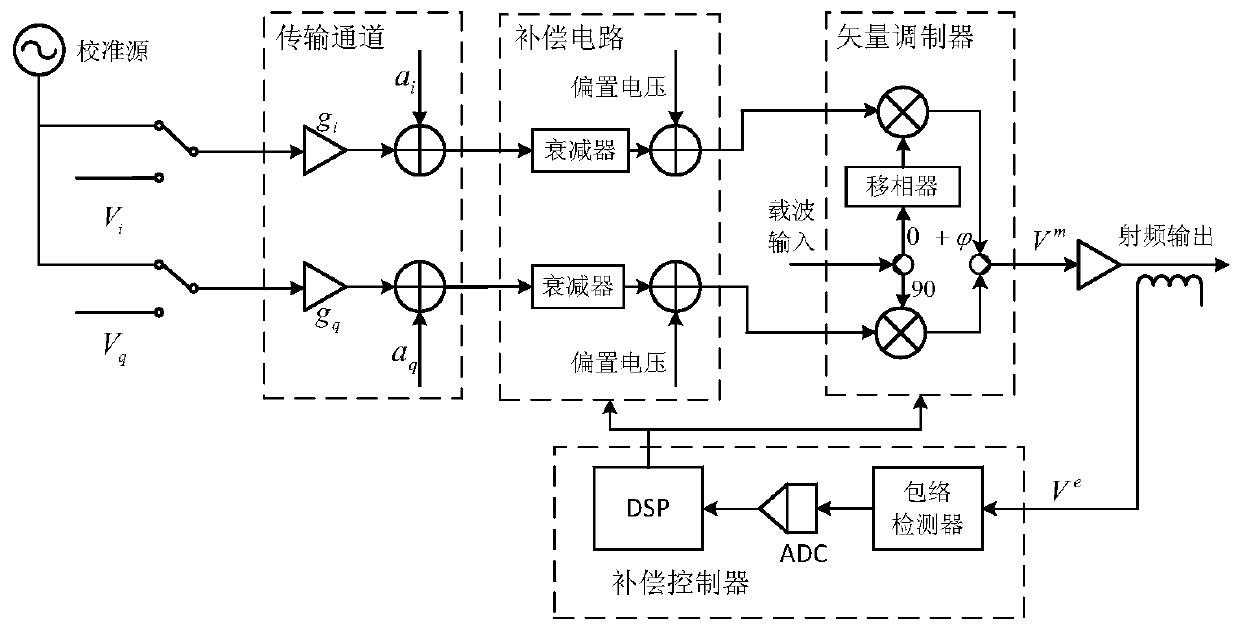
[0074] Figure 4 It is a structural diagram of an adaptive large modulation bandwidth I / Q modulation error digital compensation system according to Embodiment 2 of the present invention. As shown in the figure, the system loop is mainly composed of four parts, including: error compensator, transmission channel, vector modulator and compensation controller. Among them, the transmission channel and the vector modulator are the main generating parts of the modulation error. In a nutshell, the following three types of errors have significant impacts, namely: I / Q two-way baseband signal transmission channel gain imbalance error (in the figure, the gains are respectively represented by g i and g q Indicated), the carrier leakage caused by the DC bias component (the DC bias component in the figure is respectively represented by a i and a q Indicates) and carrier quadrature error

[0075] The compensation controller is used to detect the radio frequency output through the envel...

Embodiment 3

[0079] This embodiment provides an adaptive large modulation bandwidth I / Q modulation error digital compensation method.

[0080] This embodiment mainly considers 3 kinds of more significant modulation errors: namely: I / Q two-way baseband signal transmission channel gain unbalance error (gain is respectively used g i and g q Indicated), the carrier leakage caused by the DC bias component (the DC bias component is respectively represented by a i and a q Indicates) and carrier quadrature error

[0081] The details of the full digital predistortion vector modulation error compensation correction scheme adopted in this embodiment are as follows:

[0082] First, a compensation method at an independent frequency point is given. Considering the transmission channel and the vector modulator, the main source of vector modulation error, as a whole, the input vector can be written as: Considering the effects of the three main errors and distortions, the output modulation signal e...


PUM


Abstract

The present invention relates to the test technology field, in particular to an adaptive large modulation bandwidth I / Q modulation error digital compensation method and an adaptive large modulation bandwidth I / Q modulation error digital compensation system. The method comprises the steps of setting a baseband signal V<o> as zero; detecting the radio frequency output via an envelope detector to obtain an envelope detection value V<e>; when the envelope detection value V<e> is a minimum value, calculating a DC bias parameter B of a vector modulation error; calculating the adjustment parameters d and f; and according to the adjustment parameters d and f and the DC bias parameter B, compensating according to the following error compensators: V<c>=C(V<o>+B), wherein the V<c> is an input vector after the error compensation. According to the scheme, a baseband signal generator, a vector modulator and a transmission channel are brought into a calibration process, the errors caused by the three parts are compensate and correct simultaneously, thereby avoiding an error caused by approximate compensation in an existing technical scheme. The scheme is realized by a baseband signal predistortion digital method, thereby avoiding the bandwidth limitation of a simulation device in the existing scheme, and realizing the high precision compensation correction of a GHz magnitude large modulation bandwidth vector modulation error.

Description

technical field [0001] The invention relates to the technical field of testing, in particular to an adaptive large modulation bandwidth I / Q modulation error digital compensation method and system. Background technique [0002] In recent years, with the rapid development of high-end complex electromagnetic signal applications, digital modulation methods have been widely used in various fields such as reconnaissance, communication, and navigation. The typical mechanism of the digital modulation method in the transmitter is to use the I / Q baseband signal and carrier signal generated by digital processing components such as DSP or FPGA to complete the modulation in the vector modulator, so as to obtain the radio frequency signal for transmission or transmission. In actual application, due to the non-ideal characteristics of the vector modulator and the transmission channel, such as the inconsistency of the gain of the I / Q two-way signal transmission channel, carrier leakage and ...

Claims


Application Information

Patent Timeline
Patent Type & Authority Applications(China)
IPC IPC(8): H04L25/03H04L27/00
Inventor 台鑫徐明哲樊晓腾李增红薛晓男宣建青何攀峰刘亮
Owner THE 41ST INST OF CHINA ELECTRONICS TECH GRP
Learn More