High-resolution dense fiber grating laying method

A fiber grating and high-resolution technology, which is applied in the direction of transmitting sensing components with optical devices, can solve the problem that a single optical fiber cannot provide sufficient spatial resolution, and achieve the effect of convenient material collection and improved spatial resolution

Inactive Publication Date: 2015-09-23
8TH RES INST OF CETC
View PDF5 Cites 7 Cited by
  • Summary
  • Abstract
  • Description
  • Claims
  • Application Information

AI Technical Summary

Problems solved by technology

[0003] Fiber Bragg gratings are generally laid out with a single fiber, and can only measure physical quantities near the Bragg grating, such as: temperature, strain, pressure, displacement, pressure, torsion angle, torque (torsion stress), acceleration, current, voltage, magnetic field, Frequency, concentration, thermal expansion coefficient, vibration, etc., that is, one-dimensional spatial distribution. For the measurement of two-dimensional or three-dimensional spatial distribution, due to the limitation of the spacing of fiber gratings on a single optical fiber, a single optical fiber sometimes cannot provide enough space. resolution

Method used


Image

  • High-resolution dense fiber grating laying method
  • High-resolution dense fiber grating laying method

Examples


Embodiment Construction

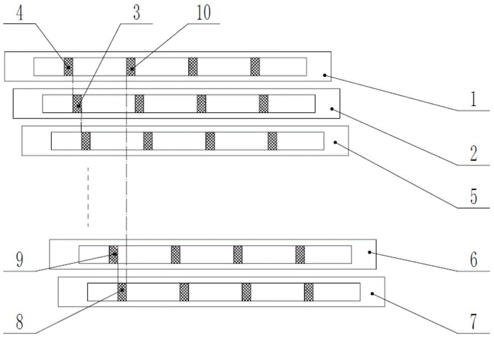
[0021] The method for laying out high-resolution dense fiber gratings of the present invention will be further described below in conjunction with the accompanying drawings and specific embodiments:

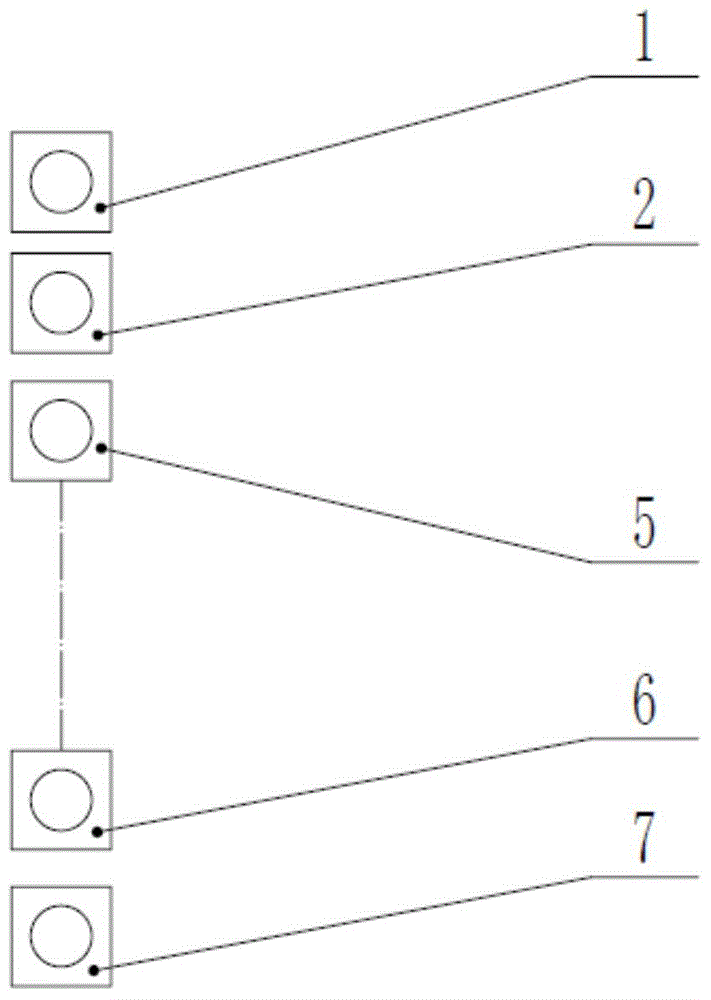
[0022] Such as figure 1 As shown, in this specific embodiment, the surface of the object to be tested is a plane where the fiber grating is to be bonded. In order to ensure that it can be decrypted and bonded with the plane, as figure 2 As shown, in this specific embodiment, the shape of the end face of each fiber Bragg grating is quadrangular. In other words, in this specific embodiment, the fiber Bragg grating is packaged in a square shape.

[0023] In this specific embodiment, the specific steps of the high-resolution dense fiber grating laying method of the present invention are as follows:

[0024] a. First, use absorbent cotton dipped in an appropriate amount of analytical pure alcohol to scrub the n optical fiber gratings to be bonded, and then put them in a drying oven ...


PUM


Abstract

The invention discloses a high-resolution dense fiber grating laying method. The method is as follows: first of all, decontamination processing is performed on fiber gratings and the surface, for bonding the fiber gratings thereto, of an object to be tested, then, the multiple fiber gratings are horizontally fixedly arranged on the surface of the object to be tested, the principle for fixed arrangement is that the multiple fiber gratings are parallel to one another, adjacent fiber gratings are spaced at proper intervals, it is ensured that apart from the first fiber grating, the initial position of a first-section Bragg raster etched on each of other fiber gratings is aligned with the tail-end position of the first-section Bragg raster etched on a previous fiber grating, and after the last fiber grating is fixedly arrangement, it should also be ensured that the tail-end position of the first-section Bragg raster etched on the last fiber grating is aligned with the initial position of a second-section Bragg raster etched on the first fiber grating. The method provided by the invention has the following advantages: materials are conveniently obtained, and the space distribution rate is greatly improved through offset arrangement.

Description

Technical field: [0001] The invention relates to the technical field of optical fiber gratings, in particular to a high-resolution dense optical fiber grating laying method which is convenient for obtaining materials and can improve spatial resolution. Background technique: [0002] Fiber Bragg grating sensors detect physical quantities such as temperature, strain, and pressure by detecting changes in wavelength, and have been successfully applied in fields such as aerospace and navigation, construction transportation, energy, chemical industry, and environmental protection. According to different structures to be tested, distributed fiber grating sensors generally use single or multiple Bragg gratings of different periods carved on a single fiber, and then after different packaging, the fiber is directly embedded, surface-mounted, and pre-packaged. On the steel plate or in the capillary, clamped and fixed at both ends, etc., the physical quantity of the fiber grating measur...

Claims


Application Information

Patent Timeline
Patent Type & Authority Applications(China)
IPC IPC(8): G01D5/26
Inventor 孙兵田国周陈群王丹凤叶杨高伍丹蕾
Owner 8TH RES INST OF CETC
Why Eureka
Try Eureka