Hooping apparatus for concrete column construction joints

A technology of concrete columns and construction joints, which is applied in the fields of formwork/formwork/work frame, on-site preparation of building components, construction, etc., to achieve the effect of ensuring implementation accuracy, tight gap sealing, and not easy to swing.

Active Publication Date: 2015-09-23
CHINA XINXING BAOXIN CONSTR CORP
View PDF6 Cites 0 Cited by
  • Summary
  • Abstract
  • Description
  • Claims
  • Application Information

AI Technical Summary

Problems solved by technology

It is easy to ensure the implementation accuracy, the dimensional deviation is not easy to exceed the allowable range of the specification, and it is not easy to cause serious appearance quality problems such as exposed ribs, honeycombs, and holes

Method used


Image

  • Hooping apparatus for concrete column construction joints
  • Hooping apparatus for concrete column construction joints
  • Hooping apparatus for concrete column construction joints

Examples


Embodiment Construction

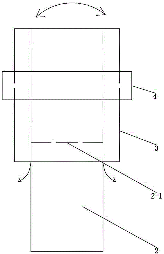
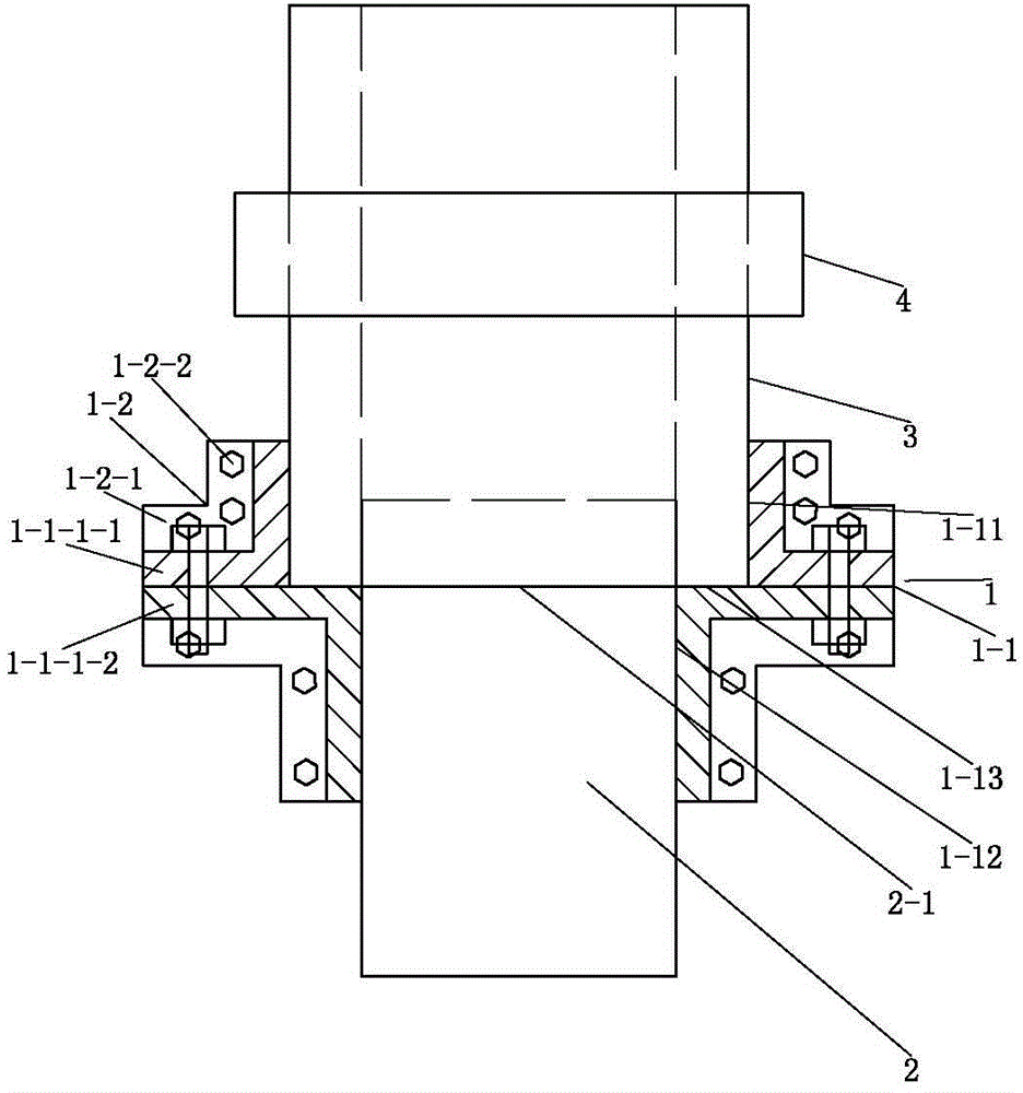
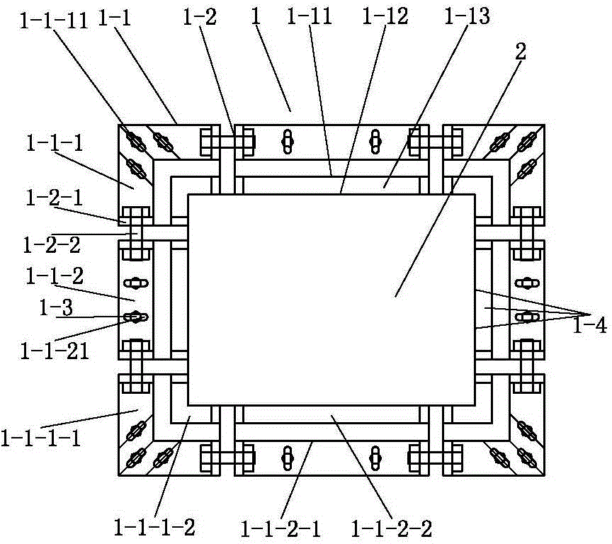
[0060] Such as Figure 2 to Figure 6 As shown, this embodiment provides a tightening device 1 at the construction joint of a concrete column, including a tightening ring 1-1, and the tightening ring 1-1 has a cylindrical formwork tightening surface for tightening the formwork 3 1-11, the cylindrical template hoop surface 1-11 used to clamp the template 3 is a cylindrical template hoop surface 1-11 used to clamp the lower end side of the template 3, the cylindrical template hoop surface The lower end edge of 1-11 shrinks inwardly to form an annular template supporting surface 1-13 for supporting the lower end surface of the template 3. The width of the annular template support surface 1-13 is adapted to the thickness of the template 3. The annular template The inner edge of the supporting surface 1-13 extends downward to form a columnar concrete column clamping surface 1-12 for clamping the upper end side of the concrete column 2.

[0061] In this embodiment, the cylindrical templ...


PUM


Abstract

The invention discloses a hooping apparatus for concrete column construction joints. The hooping apparatus comprises a hooping ring. The hooping ring is provided with a cylindrical mould hooping surface used for hooping a mould. The edge of the lower end of the cylindrical mould hooping surface contracts inwardly to form an annular mould supporting surface used for supporting the end surface of the lower end of the mould. The width of the annular mould supporting surface matches the thickness of the mould. The inner edge of the annular mould supporting surface extends downwardly to form a cylindrical concrete column hooping surface used for hooping the side surface of the upper end of a concrete column. The hooping apparatus for the concrete column construction joints can firmly connect the lower end of the mould and the upper end of the concrete column, the supported mould is not liable to swing, and gaps are tightly sealed. During a pouring process, the lower portion of the mould is not liable to expand outwardly, and the size is not liable to flow out from the bottom of the mould. According to the invention, the construction precision can be easily guaranteed, the size deviation is not liable to exceed a standard allowed range, and severe appearance quality problems such as reinforcing bar exposure, honeycombs and holes are not liable to occur.

Description

Technical field [0001] The invention relates to a fastening device for the staged support of a concrete column, in particular to a clamping device at the construction joint of the concrete column. Background technique [0002] Such as figure 1 As shown, when the height of the concrete column 2 exceeds the longest vibrating depth of the concrete vibrating rod, or when the concrete column 2 needs to be poured in stages due to other reasons, it is necessary to carry out the staged formwork. In the prior art, an upwardly extending formwork 3 is surrounded along the upper end of the concrete column 2 at a horizontal construction joint 2-1 where the concrete column 2 is connected to a high level, and the formwork clamping device 4 is used to tighten the formwork 3 in the middle. The lower part, but the template tightening device 4 is located above the horizontal construction joint 2-1, and the lower part of the template 3 is not tightened by the template tightening device 4. To put it...

Claims


Application Information

Patent Timeline
Patent Type & Authority Applications(China)
IPC IPC(8): E04G13/02
Inventor 杨兴彦王强谢继周马恒勇
Owner CHINA XINXING BAOXIN CONSTR CORP
Why Eureka
Try Eureka