
Machine tool with lubricating oil recycling function

A lubricating oil and function technology, applied in the field of machine tools with lubricating oil recovery function, can solve problems such as environmental damage, save lubricating oil costs, improve recovery efficiency, and solve the effect of waste oil discharge

Active Publication Date: 2015-09-23
蚌埠中知知识产权运营有限公司
View PDF8 Cites 2 Cited by
  • Summary
  • Abstract
  • Description
  • Claims
  • Application Information

AI Technical Summary

Problems solved by technology

[0003] During the process of machine tool processing, all parts need to be lubricated for maintenance, and the waste oil formed after the used lubricating oil overflows from the machine tool, the direct discharge of waste oil is easy to cause damage to the environment

Method used


Image

  • Machine tool with lubricating oil recycling function

Examples


Embodiment Construction

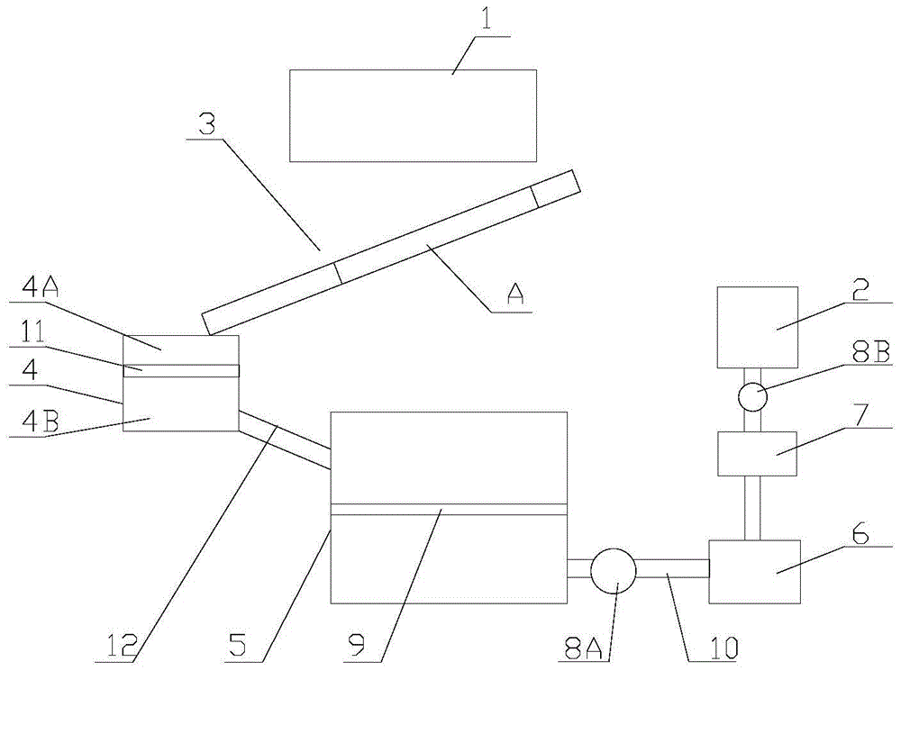
[0015] refer to figure 1 , a kind of machine tool with lubricating oil recovery function that the present invention proposes, comprises: frame, processing mechanism 1, oil storage tank 2, oil residue separating sieve plate 3, slag collecting box 4, oil collecting box 5, lubricating oil filter 6, Recovery tank 7, first suction pump 8A, and second suction pump 8B.

[0016] The processing mechanism 1 is installed on the frame for processing workpieces, and the oil storage tank 2 can provide lubricating oil to the processing mechanism 1 to lubricate parts.

[0017] The oil residue separation sieve plate 3 is obliquely installed on the frame and is located directly below the processing mechanism 1. There are multiple sieve holes on the oil residue separation sieve plate 3, and the area where the oil residue separation sieve plate 3 is equipped with sieve holes forms a filtering area. a.

[0018] The oil collection tank 5 is installed on the side of the oil residue separation siev...


PUM


Abstract

The invention provides a machine tool with a lubricating oil recycling function. The machine tool comprises a rack, a machining mechanism, an oil storage tank, an oil and slag separating screen plate, a slag collecting tank, an oil collecting tank, a lubricating oil filter, a recycling tank, a first suction pump and a second suction pump. The machining mechanism is mounted on the rack, and the oil storage tank can convey lubricating oil to the machining mechanism; the oil and slag separating screen plate is mounted on the rack in an inclining manner and is located under the machining mechanism; and a plurality of screen holes are formed in the oil and slag separating screen plate; the slag collecting tank is mounted at the lower end of the oil and slag separating screen plate, and the oil collecting tank is mounted on one side, close to the ground, of the oil and slag separating screen plate; a first screen net is arranged in the oil collecting tank, and an output pipe is arranged on the oil collecting tank; the output pipe is communicated with an oil inlet end of the lubricating oil filter; and the oil outlet end of the lubricating oil filter is communicated with the recycling tank, and the oil storage tank is communicated with the recycling tank through the second suction pump. Lubricating oil is circularly utilized, lubricating oil cost is saved, and the problem of waste oil draining is solved.

Description

technical field [0001] The invention relates to the technical field of machine tools, in particular to a machine tool with lubricating oil recovery function. Background technique [0002] A machine tool is a machine that processes metal blanks into machine parts. It is a machine for manufacturing machines, so it is also called a working machine or a machine tool. In modern machinery manufacturing, there are many ways to process parts, but the parts with high precision and surface roughness requirements generally need to be final processed by cutting on the machine tool. [0003] During the process of machine tool processing, each component needs to be lubricated for maintenance, and the waste oil formed after the used lubricating oil overflows from the machine tool, and the waste oil is easily discharged directly to cause damage to the environment. Contents of the invention [0004] Based on the technical problems existing in the background technology, the present inventi...

Claims


Application Information

Patent Timeline
Patent Type & Authority Applications(China)
IPC IPC(8): B23Q11/12
CPCB23Q11/12
Inventor 林锦富
Owner 蚌埠中知知识产权运营有限公司
Learn More