Pulse frequency multiplier circuit

A technology of frequency multiplier and circuit, applied in the field of pulse frequency multiplier circuit, to achieve the effect of simple structure and low cost

Inactive Publication Date: 2015-09-16
SUZHOU GUJI ELECTRONICS TECH
View PDF2 Cites 2 Cited by
  • Summary
  • Abstract
  • Description
  • Claims
  • Application Information

AI Technical Summary

Problems solved by technology

At present, the commonly used circuits use larger integrated circuits,

Method used


Image

  • Pulse frequency multiplier circuit

Examples


Embodiment Construction

[0013] The present invention will be further described below in conjunction with the accompanying drawings.

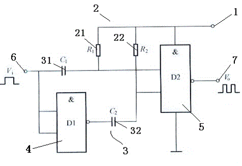
[0014] Such as figure 1 As shown, a pulse frequency multiplier circuit includes a voltage input terminal 1, a resistor 2, a capacitor 3, a first NAND gate 4, a second NAND gate 5, a signal input terminal 6, and a signal output terminal 7. The resistor 2 includes a first resistor 21 and a second resistor 22, the capacitor includes a first capacitor 31 and a second capacitor 32, the signal input terminal 6 is connected to the two input terminals of the first NAND gate 4, the first NAND The output terminal of gate 4 is connected in series with the second capacitor 32, the second resistor 22, the voltage input terminal 1 and then an input terminal of the second NAND gate 5; the signal input terminal 6 is connected with the first capacitor 31, the first resistor 21, the voltage The input terminal 1 is connected in series to the other input terminal of the second NAND gate ...


PUM


Abstract

Disclosed in the invention is a pulse frequency multiplier circuit comprising a voltage input terminal, a resistor, a capacitor, a first NAND gate, a second NAND gate, a signal input terminal, and a signal output terminal. The resistor includes a first resistor and a second resistor; and the capacitor contains a first capacitor and a second capacitor. The signal input terminal is connected with two input terminals of the first NAND gate; an output terminal of the first NAND gate is connected in series with the second capacitor, the second resistor and the voltage input terminal and then is connected with an input terminal of the second NAND gate; the signal input terminal is connected in series with the first capacitor, the first resistor, and the voltage input terminal and then is connected with another input terminal of the second NAND gate; and an output terminal of the second NAND gate serves as a signal output terminal. According to the pulse frequency multiplier circuit, two NAND gates are used and frequency doubling of the input signal can be realized. Moreover, the structure is simple and the cost is low; and the circuit is suitable for various small electronic products.

Description

technical field [0001] The invention relates to a pulse frequency multiplier circuit, belonging to the technical field of frequency multiplier circuits. Background technique [0002] A frequency multiplier is a circuit that makes the output signal frequency equal to an integer multiple of the input signal frequency. The input frequency is f1, then the output frequency is f0=nf1, and the coefficient n is any positive integer, which is called the number of times of multiplication. The frequency multiplier has a wide range of uses, such as the transmitter can make the main oscillator oscillate at a lower frequency to improve frequency stability; the frequency multiplier is used to increase the frequency offset in the frequency modulation equipment; Among them, the frequency multiplier is an important component of the carrier recovery circuit. At present, the commonly used circuits use larger integrated circuits, which are not suitable for low-cost, simple-function electronic ...

Claims


Application Information

Patent Timeline
IPC IPC(8): H03K3/78
Inventor 罗宇新
Owner SUZHOU GUJI ELECTRONICS TECH
Why Eureka
Try Eureka