
Conformal thin film of precious metal on support

A precious metal and substrate technology, applied to structural parts, electrical components, battery electrodes, etc., can solve problems such as uneven line-of-sight characteristics of sputtered films

Active Publication Date: 2015-09-16
GM GLOBAL TECH OPERATIONS LLC
View PDF5 Cites 5 Cited by
  • Summary
  • Abstract
  • Description
  • Claims
  • Application Information

AI Technical Summary

Problems solved by technology

Some prior art sputtered films were observed to be non-uniform due to the line-of-sight nature of the sputtering process

Method used


Image

  • Conformal thin film of precious metal on support
  • Conformal thin film of precious metal on support
  • Conformal thin film of precious metal on support

Examples


Embodiment Construction

[0043] Reference will now be made in detail to presently preferred compositions, embodiments and methods of the invention which constitute the best modes currently known to the inventors for carrying out the invention. The drawings are not necessarily to scale. It should be understood, however, that the disclosed embodiments are merely exemplary of the invention that can be embodied in various and alternative forms. Therefore, specific details disclosed herein are not to be interpreted as limiting, but merely as a representative basis for any aspect of the invention and / or as a representative basis for teaching one skilled in the art to variously employ the invention.

[0044]Except in the examples, or unless expressly indicated otherwise, all numerical quantities in this description indicating the amount of materials or conditions reacted and / or employed are to be understood as being indicated by the word "about "Retouch. Practice within the numerical limits stated is gener...


PUM

PropertyMeasurementUnit
Thicknessaaaaaaaaaa

Abstract

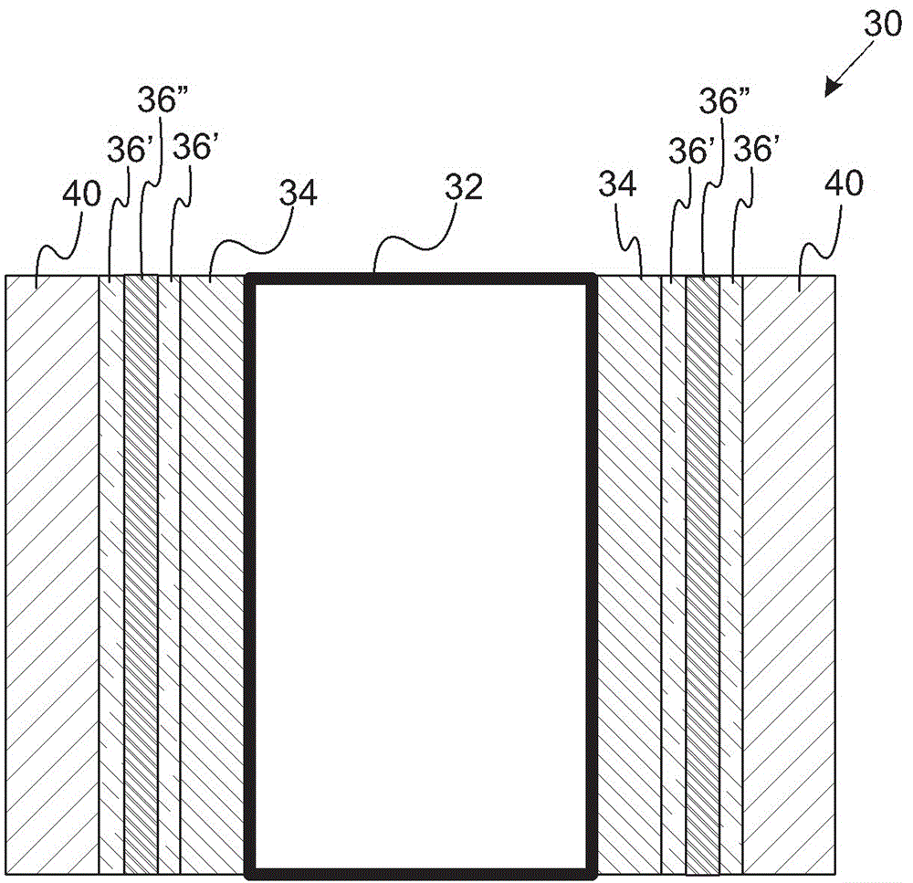
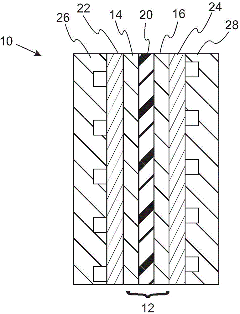
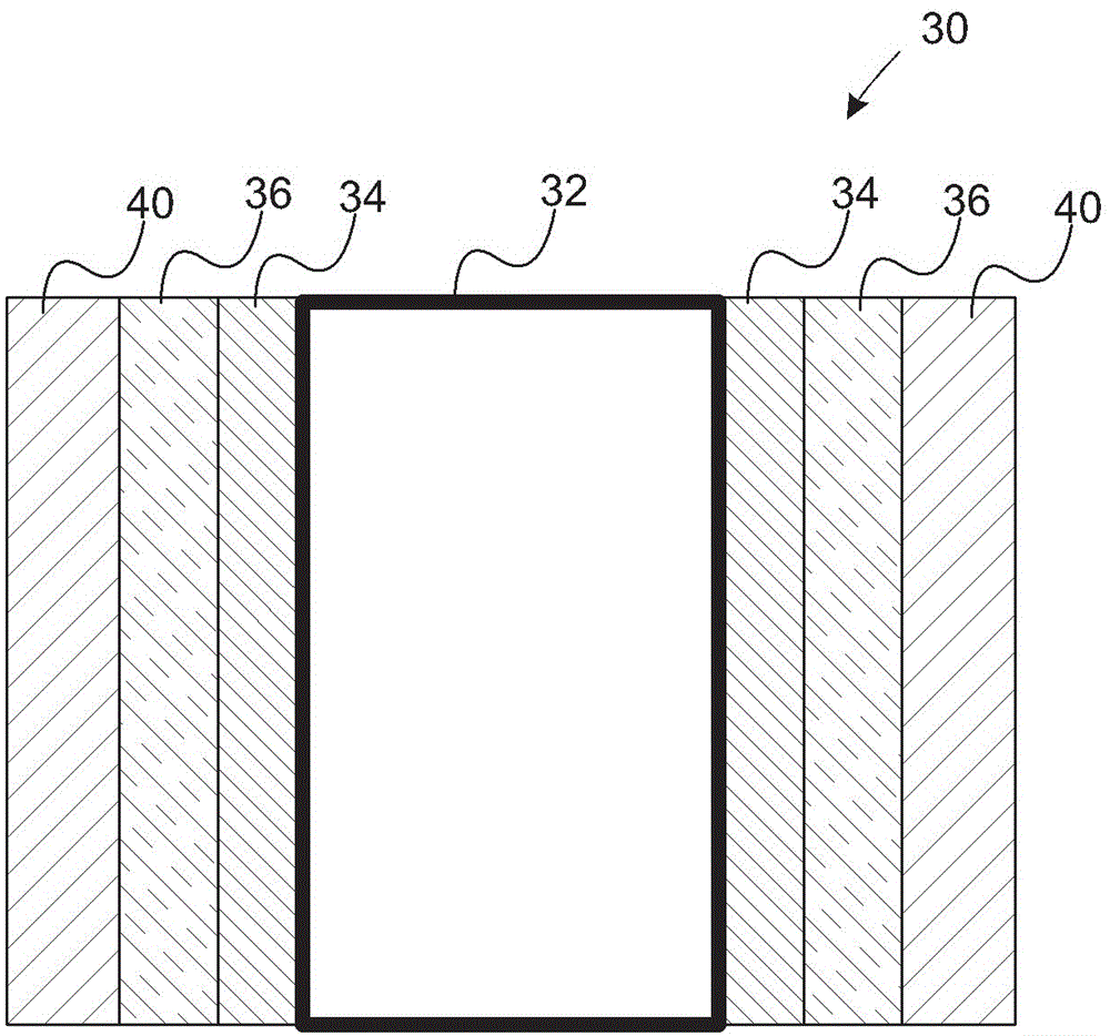
A coated substrate for forming fuel cell catalyst layers includes a plurality of substrate particles, an adhesion layer disposed over the substrate particles, and a precious metal layer disposed over the adhesion layer. The adhesion layer includes a tungsten metal layer. Characteristically, the coated substrate is used in fuel cell applications such as providing the catalyst particles used in the cathode and / or anode catalyst layers.

Description

[0001] Cross References to Related Applications [0002] This application claims the benefit of US Provisional Application Serial No. 61 / 915,731 filed December 13, 2013, the disclosure of which is incorporated herein by reference in its entirety. technical field [0003] In at least one aspect, the invention relates to catalyst layers for use in fuel cell applications. Background technique [0004] Fuel cells are used as power sources in many applications. Specifically, fuel cells are proposed to be used in automobiles in place of internal combustion engines. Commonly used fuel cell designs use a solid polymer electrolyte ("SPE") membrane or a proton exchange membrane ("PEM") to provide ion transport between the anode and cathode. [0005] In a fuel cell of the proton exchange membrane type, hydrogen is supplied to the anode as a fuel, and oxygen is supplied to the cathode as an oxidant. Oxygen can be in pure form (O 2 ) or air (O 2 with N 2 mixture). PEM fuel cells t...

Claims


Application Information

Patent Timeline
IPC IPC(8): H01M4/92H01M4/86
CPCH01M4/926H01M4/9041H01M4/9075H01M4/8657H01M4/9083H01M4/925Y02E60/50
Inventor A.康格卡南德R.S.库克雷雅J.W.克兰西A.卡瓦瑙格S.M.乔治
Owner GM GLOBAL TECH OPERATIONS LLC
Learn More