Cylindrical wind generator with multi-stage impeller set

A technology of wind power generator and impeller group, which is applied in the direction of wind power generator, wind power motor, wind power motor combination and other directions consistent with the wind direction, and can solve the problems of low annual utilization hours, increased swing of fuselage tower, self-height, weight, Volume increase and other issues, to achieve the effect of reducing natural erosion or the probability of blades being struck by lightning, reducing mechanical failure rate, and reducing the cost of the whole machine

Active Publication Date: 2017-12-22
张家口茂盛创新科技有限公司
View PDF11 Cites 0 Cited by
  • Summary
  • Abstract
  • Description
  • Claims
  • Application Information

AI Technical Summary

Problems solved by technology

This type of wind turbine is limited by its structure, and its output power is closely related to the sweeping area of ​​the blades. That is, to increase the rated output power, it usually requires increasing the length of the blades to increase the sweeping area of ​​the blades. Therefore, when the power of the fan increases, its The height, weight, and volume of the machine itself increase accordingly, and the tall fuselage tower increases the overall swing, which reduces its wind resistance, and the structure and material strength of the equipment are high, and the overall cost, operation and daily maintenance Expenses have increased substantially
[0003] In addition, in order to avoid turbulence among the fans, the distance between the fans should be set to be greater than 8 times the height of the fans themselves. The wind field occupies a large area and the land utilization rate is not high. Take the current rated power of 1.5MW as an example: The height of the whole machine is more than 100 meters, the length of a single blade is about 45 meters, and the weight of only the head is up to 100 tons. is 25m / s, the cut-in and cut-out wind speed is the effective wind speed), there is a waste of wind resources, and the cost of electricity per kilowatt increases. Therefore, the current wind power equipment has a large investment, a long cost recovery cycle, and the annual utilization hours are low ( Generally 2000-3000 hours), that is, the actual working time of the wind turbine is only 1 / 3 of the whole year, and the return on investment of the wind farm is about 10 years
The above reasons directly lead to the fact that the unit cost of wind power is higher than that of other power generation methods (such as thermal power generation); during the operation of the fan with the above structure, the stress is concentrated on the root of the blade when the impeller decelerates or suddenly brakes, and the blade is more likely to be damaged. , in addition, the blades have a higher probability of being broken by lightning strikes

Method used


Image

  • Cylindrical wind generator with multi-stage impeller set
  • Cylindrical wind generator with multi-stage impeller set
  • Cylindrical wind generator with multi-stage impeller set

Examples


Embodiment 1

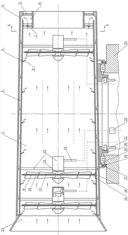
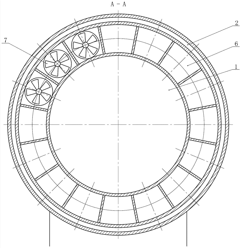
[0028] From Figure 1 ~ Figure 3 It can be seen that the technical solution of the present invention includes the base and the generator set arranged inside the base; the present invention also includes the air duct 1, the shaft frame 12, the impeller group, the return air duct 2, the braking device, and the yaw mechanism;

[0029] The air cylinder 1 is assembled on the top of the base 23 through a yaw mechanism; the yaw mechanism includes an arc-shaped guide rail 18, a guide hook wheel 17, a thrust bearing group 19, and a ring gear 20; the lower part of the air cylinder 1 is equipped with a guide hook wheel 17 and the ring gear 20; the arc-shaped guide rail 18 is fixed on the top of the base 23; the base 23 and the lower part of the blower 1 are slidably matched through the thrust bearing group 19, and the guide hook wheel 17 is clamped in the arc-shaped guide rail 18 and rolls with the guide rail Cooperate to prevent the fan cylinder from tilting; the ring gear 20 is connect...

Embodiment 2

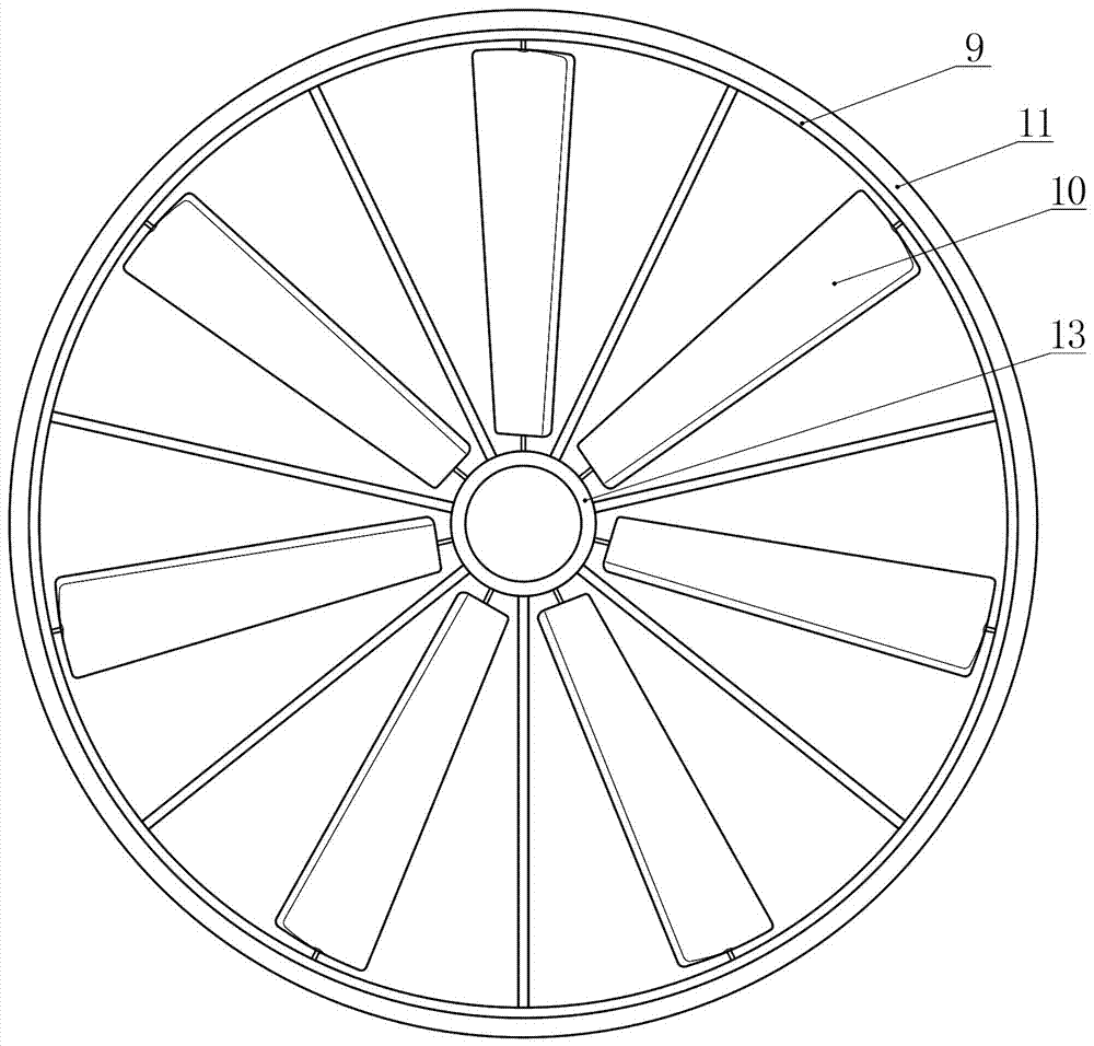
[0036] From Figure 4 It can be seen that the difference between this embodiment and Embodiment 1 is that a limit device is installed on the rear side of the annular frame 9 of each impeller group, and the limit device includes a limit roller 25 and an annular slideway fixed on the inner wall of the air duct 26. The limit roller 25 is rollingly matched with the annular slideway 26. It can prevent the annular frame 9 and the blade body from receding deformation due to the stress of the impeller. According to the material and operating conditions of the whole machine, the connection mode between the brake caliper 16 and the air duct can also be fixedly connected.

[0037] Figure 5 As shown, in this embodiment, the booster fan 7 is installed at the inlet of the return air duct at the side of the air collection duct to ensure the air circulation of the air collection duct 6 when the exhaust door 5 is fully opened.

[0038] Other technical features of this embodiment are the sam...


PUM


Abstract

The invention relates to the technical field of wind power generation devices, in particular to a barrel type wind power generator with multiple impeller units. According to an existing three-blade horizontal-axis wind turbine, the power is limited by the structure, the utilization rate per year is low, and generating cost is high. The barrel type wind power generator comprises a base, generator sets, an air duct, the impeller units, a backflow air flue, brake devices and a yaw mechanism. The air duct is arranged on the top of the base through the yaw mechanism, the impeller units are coaxially arranged in the air duct, and each impeller unit drives the corresponding generator set. The brake devices are arranged at the outer ends of the impeller units, the backflow air flue is arranged on the outer wall of the air duct in a surrounding mode, so that airflow flowing through the inside of the air duct circulates to the front portion of each impeller unit, and impellers are assisted in rotating. According to the barrel type wind power generator, the impeller units are arranged in the single air duct and drive the multiple generator sets to work, air flows back through the air duct structure, the effective air speed range is widened, all-weather operation is achieved, power generation efficiency and the land utilization rate for installation are improved, and cost of per-unit electric energy is lowered.

Description

technical field [0001] The invention relates to the technical field of wind power generation equipment, in particular to a cylindrical wind power generator with multi-stage impeller sets. Background technique [0002] Wind power generators have the characteristics of environmental protection and no pollution, and have been widely used. At present, most wind turbines are in the form of horizontal axis three blades, installed on the top of the tower, using natural wind energy to drive the impeller, and drive the generator set through the transmission system to convert wind energy into mechanical energy for power generation. This type of wind turbine is limited by its structure, and its output power is closely related to the sweeping area of ​​the blades. That is, to increase the rated output power, it usually requires increasing the length of the blades to increase the sweeping area of ​​the blades. Therefore, when the power of the fan increases, its The height, weight, and v...

Claims


Application Information

Patent Timeline
Patent Type & Authority Patents(China)
IPC IPC(8): F03D9/25F03D7/02F03D7/04F03D1/04F03D1/06
CPCY02E10/72Y02E10/728
Inventor 王茂成王峰
Owner 张家口茂盛创新科技有限公司
Why Eureka
Try Eureka