Diversion drainage structure for tunnel inside in water conservancy and hydropower project and construction method of diversion drainage structure

A drainage structure, water conservancy and hydropower technology, which is applied in the construction of the above-mentioned diversion and drainage structure and in the field of diversion and drainage structure, can solve the problems of prolonging the construction period, increasing the project investment, waste of materials, etc., so as to shorten the construction period and reduce the construction investment. Cost and effect of reducing construction length

Active Publication Date: 2015-09-16
POWERCHINA CHENGDU ENG
View PDF5 Cites 5 Cited by
  • Summary
  • Abstract
  • Description
  • Claims
  • Application Information

AI Technical Summary

Problems solved by technology

However, due to site needs and other reasons, the inlet of the drainage hole needs to be moved upstream. If a new drainage hole is built at this time, the original drainage hole will flow through before the new drainage hole is completed. This diversion and drainage method not only requires a large project investment, but also And the construction period is significantly extended
In this way, it can neither meet the requirements of the construction period, but also cause an unplanned increase in project investment. At the same time, it is also a serious waste of materials, which is not conducive to the needs of environmental protection and low-carbon construction.

Method used


Image

  • Diversion drainage structure for tunnel inside in water conservancy and hydropower project and construction method of diversion drainage structure

Examples


Embodiment Construction

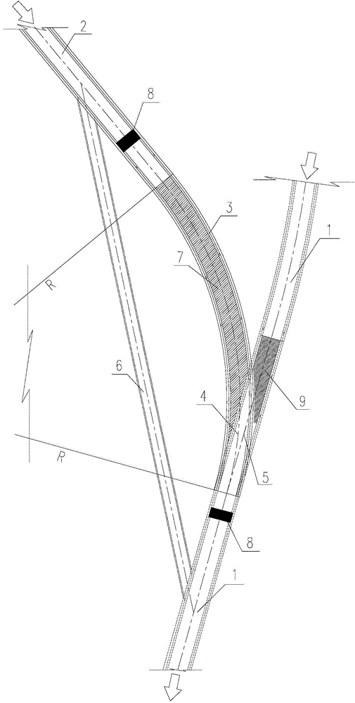
[0017] Such as figure 1 Shown is a diversion and drainage structure used in water conservancy and hydropower engineering holes that has a short construction period, low construction investment cost, and can satisfy the upward movement of the diversion and drainage hole, and a kind of diversion and drainage structure for the construction of the above-mentioned drainage structure. Construction method of drainage structure. The diversion and drainage structure includes a drainage hole body 1 arranged in the rock body, and the diversion and drainage structure also includes a drainage tunnel 2 arranged on the upstream side of the drainage hole body 1 along the river flow direction. The tail end of the tunnel 2 communicates with the drainage tunnel body 1 according to the set position in the rock body. In the above embodiment, in combination with the characteristics of hydraulics, in order to reduce the erosion of the water flow on the connection between the drainage tunnel 2 and t...


PUM


Abstract

The invention discloses a diversion drainage structure for a tunnel inside in a water conservancy and hydropower project and a construction method for building the diversion drainage structure, and belongs to the technical field of design and construction of buildings in the water conservancy and hydropower project. The invention provides the diversion drainage structure for the tunnel inside in the water conservancy and hydropower project and the construction of the building construction method. The diversion drainage structure for the tunnel inside in the water conservancy and hydropower project is short in construction period, low in construction investment cost and capable of meeting the requirement of upward moving of an opening of a diversion drainage tunnel. The construction method includes that a section of a drainage tunnel is constructed on the upstream side of a drainage tunnel body in a river flow direction, a construction maintenance diversion tunnel which communicates the drainage tunnel and the drainage tunnel body is constructed before the drainage tunnel and the drainage tunnel body are communicated, the requirement for temporary diversion drainage of an upstream river channel is met, then the connection position of the drainage tunnel and the drainage tunnel body is completely broken through, a waste upper section of the drainage tunnel body is blocked, finally, simultaneous drainage of the drainage tunnel and the downstream section of the drainage tunnel body as well as the drainage tunnel, the construction maintenance diversion tunnel and the downstream section of the drainage tunnel body is realized.

Description

technical field [0001] The invention relates to a diversion and drainage structure, in particular to a diversion and drainage structure used in water conservancy and hydropower engineering caves, and belongs to the technical field of design and manufacture of water conservancy and hydropower engineering buildings. The present invention also relates to a construction method for constructing the above-mentioned diversion and drainage structure. Background technique [0002] At present, in the construction of water conservancy and hydropower projects, after retaining dams and drainage tunnels are built in the river course, the drainage tunnel built will flow through, and the original river course can no longer flow through. However, due to site needs and other reasons, the inlet of the drainage hole needs to be moved upstream. If a new drainage hole is built at this time, the original drainage hole will flow through before the new drainage hole is completed. This diversion and ...

Claims


Application Information

Patent Timeline
IPC IPC(8): E02B9/06
CPCY02E10/20
Inventor 雷运华王小波余挺金伟何兴勇曹驾云李国琼冯菊
Owner POWERCHINA CHENGDU ENG
Why Eureka
Try Eureka