


Quick Research
Generate reliable direction feasibility study reports for your R&D in just a few steps.

Technical Q&A
Discover and master advanced knowledge NOW. Basics, ideas, possibilities, all at once.

Find Solutions
As an expert in R&D theories, this can generate solutions to your technical problems instantly.

Evaluate Feasibility
Analyze your overall solution with one click, know your potential R&D risks in advance.

Monitor Landscape
Get weekly tech updates, stay abreast of the latest tech innovations and key insights.
Gas well fracturing flow-back fluid separation device
A fracturing flowback fluid and separation device technology, applied in degassed water/sewage treatment, mining wastewater treatment, etc., can solve the problems of diffuse flammable gas, not easy separation of sprayed liquid, deflagration, etc. Corrosion, easy maintenance, energy saving effect
- Summary
- Abstract
- Description
- Claims
- Application Information
AI Technical Summary
Problems solved by technology
Method used
Image

Examples
Embodiment 1
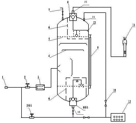
[0030] In order to solve the problem of rapid and complete separation of high-pressure gas and solid-liquid mixture in the flowback process after gas well pressure, the present invention provides such figure 1 The gas well backflow gas-liquid separation device shown in the gas well fracturing backflow operation separates liquid, gas, and sand, and realizes that when the gas-liquid ratio is large or small, only liquid can flow out of the liquid outlet. The mouth can only breathe out.
[0031] A gas well fracturing flowback liquid separation device, comprising a gas-liquid separation tank 12, an upper floating ball valve 8 is provided at the gas outlet 15 on the upper part of the gas-liquid separation tank 12, and a lower floating ball valve 801 is provided at the lower liquid outlet 16, the A baffle separation plate 4 is arranged between the upper floating ball valve 8 and the lower floating ball valve 801; the inlet on one side of the gas-liquid separation tank 12 is connected...
Embodiment 2
[0040] Based on the basis of Embodiment 1, the gas collector 11 will ignite or discharge the separated gas to the gathering station.
[0041] The upper part of the gas-liquid separation tank 12 is also provided with a safety valve 7 .
[0042] The safety valve 7 is when the pressure exceeds the set rated pressure, the safety valve 7 opens to release the pressure. In this embodiment, the rated pressure is 4MPa.
[0043]The upper overflow outlet of the gas-liquid separation tank 12 is connected to the liquid-solid separator 13 through a pipeline, and an overflow valve 10 is arranged on the pipeline.
[0044] A first restrictor 2 is provided between the flowback liquid inlet 1 and the energy dissipator 3 .
[0045] A second restrictor 201 is provided between the liquid-solid separator 13 and the flowback liquid inlet 1 .
[0046] Among them, the first restrictor 2 automatically adjusts the flow rate entering the gas-liquid separation tank, prevents the separation tank from ove...
Embodiment 3
[0058] On the basis of embodiment 1 and embodiment 2, the design calculation of gas outlet 15 and the diameter of bottom liquid outlet 16 of gas-liquid separation tank 12
[0059] (1) Design purpose: to ensure that the gas-liquid separation tank 12 has a certain throttling capacity, and the working pressure reaches 2 MPa for separation.
[0060] (2) Design basis: The maximum flow rate of pure liquid is 1 cubic meter per minute when the gas well blows out; when the gas-liquid ratio reaches more than 50% in the middle and late stages of blowout, the maximum flow rate of gas in the mixed liquid is ≤100,000 cubic meters / day; the maximum pressure bearing capacity of the gas-liquid separation tank 12 is 4 MPa, the working pressure is 2 MPa, and the safety factor is 2.0. According to these parameters, the parameters of the gas outlet 15 and the liquid outlet 16 of the gas-liquid separation tank 12 are designed and calculated .
[0061] (3) Calculation of the gas outlet diameter of...
PUM
 Abstract
Description
Claims
Application Information
 - R&D Engineer
- R&D Manager
- IP Professional
- Industry Leading Data Capabilities
- Powerful AI technology
- Patent DNA Extraction
Browse by: Latest US Patents, China's latest patents, Technical Efficacy Thesaurus, Application Domain, Technology Topic, Popular Technical Reports.
© 2024 PatSnap. All rights reserved.Legal|Privacy policy|Modern Slavery Act Transparency Statement|Sitemap|About US| Contact US: help@patsnap.com