Anticoagulation liquid-stopping transfusion device with liquid-stopping sealant floating plug balloon catheter

A technology of rubber plug capsule tube and gel plug capsule, which is applied in the direction of devices introduced into the body, flow monitors, hypodermic injection devices, etc., and can solve the problems of infusion waste and other problems

Inactive Publication Date: 2015-09-16
戎静华
View PDF8 Cites 0 Cited by
  • Summary
  • Abstract
  • Description
  • Claims
  • Application Information

AI Technical Summary

Problems solved by technology

[0004] In order to overcome the above-mentioned deficiencies of the hemostatic infusion set, the present invention proposes an anticoagulant hemostatic infusion set with a hemostatic sealant floating plug capsule tube, which can make the hemostatic infusion set make the intravenous injection needle stop when the liquid is stopped. Within a few hours, a small amount of infusion can be infused into the vein, so it can not only avoid the above-mentioned blood coagulation at the intravenous injection needle due to the long time of stopping the liquid, but also prevent the infusion tube from getting air, In addition, if the nurse handles the infusion set in time, it can avoid the waste of infusion caused by the infusion of the residual infusion in the dripping funnel due to the short stop time.

Method used


Image

  • Anticoagulation liquid-stopping transfusion device with liquid-stopping sealant floating plug balloon catheter
  • Anticoagulation liquid-stopping transfusion device with liquid-stopping sealant floating plug balloon catheter
  • Anticoagulation liquid-stopping transfusion device with liquid-stopping sealant floating plug balloon catheter

Examples


Embodiment 1

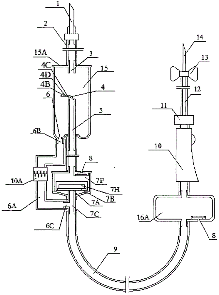
[0020] Such as figure 1 Shown is a central longitudinal sectional view of an anticoagulant hemostatic infusion set with a liquid storage bag and a drip funnel combined with a liquid stopper sealant floating stopper tube, the bottle stopper piercer 1 is connected to the upper infusion tube 2. The upper infusion tube 2 is connected to the dropper 3, and the dropper 3 is connected to the dropper cover 15A.

[0021] In the lower neck of the dripping funnel 15, one is inserted into the cavity of the dripping funnel 15, and the two ends are provided with an open, internally hollow exhaust pipe 5, and the upper end of the side wall of the exhaust pipe 5 is provided with an exhaust hole. 4C, the position of the exhaust hole 4C is located between 1 / 2~2 / 3 of the height of the drip funnel. The upper bottom surface of the exhaust pipe 5 is a drainage slope 4 arranged in a direction away from the exhaust hole 4C. At the edge of the drainage slope 4 on the side of the exhaust hole 4C, a l...

Embodiment 2

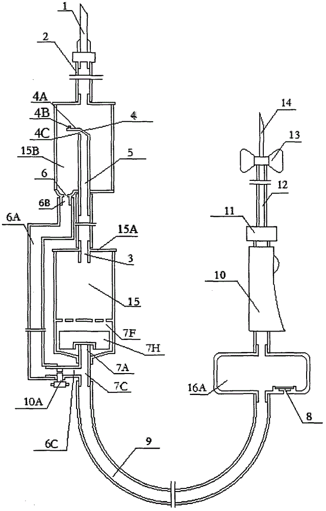
[0035] Such as figure 2 Shown is a central longitudinal sectional view of an anticoagulant hemostatic infusion set with a liquid-stopping sealant floating plug capsule tube with a liquid storage bag independent, a drip funnel and a liquid-stopping sealed capsule tube integrated into one. The bottle stopper piercer 1 is connected with the upper infusion tube 2, and the upper infusion tube 2 is connected with the upper neck of the liquid storage bag 15B.

[0036] In the lower neck of the liquid storage bag 15B, one is inserted into the cavity of the liquid storage bag 15B, and the two ends are provided with an open, internally hollow exhaust pipe 5. There is an exhaust pipe at the upper end of the side wall of the exhaust pipe 5. Hole 4C, the position of exhaust hole 4C is located between the high 1 / 2~2 / 5 of the drip funnel. The upper bottom surface of the exhaust pipe 5 is a drainage slope 4 arranged in a direction away from the exhaust hole 4C. At the edge of the drainage s...

Embodiment 3

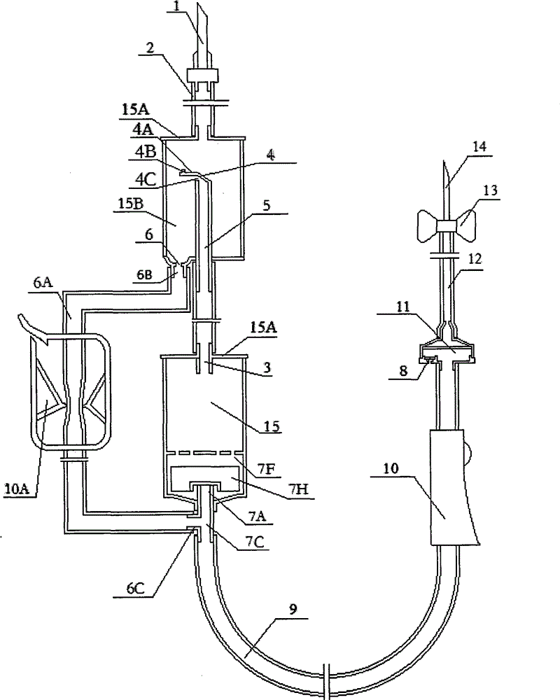
[0043] Such as image 3 Shown is a central longitudinal sectional view of an anticoagulant hemostatic infusion set with a liquid-stop sealant floating plug capsule tube in which the dropping funnel and the liquid-stop sealed capsule tube are combined into one. The bottle stopper piercer 1 is connected with the upper infusion tube 2, and the upper infusion tube 2 is connected with the upper neck of the liquid storage bag 15B.

[0044] In the lower neck of the liquid storage bag 15B, one is inserted into the cavity of the drip funnel 15, and the two ends are provided with an open, internally hollow exhaust pipe 5, and an exhaust hole is arranged at the upper end of the side wall of the exhaust pipe 5. 4C, the position of the exhaust hole 4C is located between 1 / 2~2 / 5 of the height of the drip funnel. The upper bottom surface of the exhaust pipe 5 is a drainage slope 4 arranged in a direction away from the exhaust hole 4C. At the edge of the drainage slope 4 on the side of the ...


PUM


Abstract

The invention discloses an anticoagulation liquid-stopping transfusion device with a liquid-stopping sealant floating plug balloon catheter, which comprises a bottle stopper puncture device, an upper infusion tube, a droplet bucket, a lower infusion tube, a flow regulator, an outer cone connector, a capillary infusion tube, a flank and an intravenous injection needle. The transfusion device is characterized in that the transfusion device also comprises a liquid storage capsule that has a lower neck provided with an exhaust pipe upward, and has a liquid-guiding aperture on a lower collet; a liquid-stopping sealant floating plug balloon catheter set below the liquid storage capsule; a drainage tube that connects the liquid-guiding aperture and the second protruding pipe below the liquid-stopping sealant floating plug balloon catheter; an anti-bubble tube set in the lower infusion tube; and a flow transposing device set between the liquid-guiding aperture and the second protruding pipe that can convert the transfusion flow from microfluidic to non-microfluidic. According to the invention, the transfusion device can stop the liquid automatically; when the liquid is stopped, the blood clotting block won't be generated at the intravenous route needle place because of long off time; and the waste of transfusion in the liquid storage capsule because of short liquid stopping time is avoided; besides, the air is prevented from getting into the lower infusion tube.

Description

【Technical field】 [0001] The invention relates to a one-time use infusion set, and is especially suitable for a one-time use anticoagulant hemostatic liquid infusion set. 【Background technique】 [0002] At present, some liquid stopper infusion devices, after stop liquid start, just do not have transfusion to be transfused into the vein under the intravenous injection needle again. In general patients, after a period of hemostasis, if there is no nurse to deal with it, there will be blood clots at the intravenous injection needle; in addition, almost all severe patients with diseases will cause blood coagulation disorders, if this This kind of patient uses stop liquid infusion set, after stop liquid, in a short time, blood coagulation will take place in intravenous injection needle. Once a blood clot occurs, it will panic the patient and even cause disputes between doctors and patients. [0003] In order to overcome the above-mentioned defects, a liquid storage bag is arran...

Claims


Application Information

Patent Timeline
IPC IPC(8): A61M5/14A61M5/36
CPCA61M5/14A61M5/16804A61M5/16877A61M5/365A61M2005/1401
Inventor 戎静华
Owner 戎静华
Why Eureka
Try Eureka