
LED driver circuits that reduce observable optical flicker by reducing rectified ac power grid ripple using a flyback converter

A driver circuit and reverse converter technology, applied in the field of driver circuits, can solve the problem of increasing the statistical failure rate of PSU

Inactive Publication Date: 2017-03-15
艾酷瑞克有限责任公司
View PDF6 Cites 0 Cited by
  • Summary
  • Abstract
  • Description
  • Claims
  • Application Information

AI Technical Summary

Problems solved by technology

Using a high value electrolytic capacitor or several low value electrolytic capacitors increases the expected rate of capacitor failure within a statistically significant sample of such PSUs and therefore increases the PSU's statistical failure rate

Method used


Image

  • LED driver circuits that reduce observable optical flicker by reducing rectified ac power grid ripple using a flyback converter
  • LED driver circuits that reduce observable optical flicker by reducing rectified ac power grid ripple using a flyback converter
  • LED driver circuits that reduce observable optical flicker by reducing rectified ac power grid ripple using a flyback converter

Examples


example

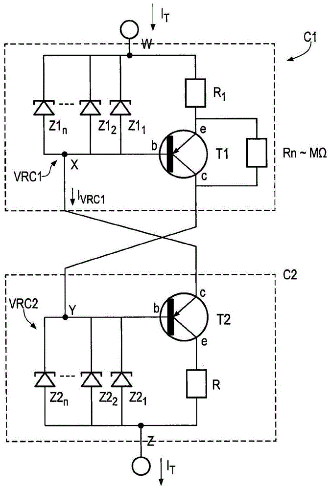
[0080] The following examples of embodiments of the present invention are for illustrative purposes and it should be apparent to the reader that limiting by output voltage from the PSU section, current drawn by the LED strings, and supply voltage and frequency can be achieved in many other embodiments and Illustrative example.

[0081] This or any other example of the invention is explained in terms of relevant design parameters of the PSU section and the current regulator section of the LED driver.

[0082] The peak output voltage of the PSU section of the driver is given by:

[0083] Vop=Vinp×N×Dp / (I-Dp) Equation (14)

[0084] where Dp is the peak duty cycle of the switching action of the switching MOSFET, and Vinp is the peak value of the full-wave rectified single-phase supply voltage, which is given by:

[0085] Equation (15)

[0086] where Vrms is the rms supply voltage and vd is the voltage drop across a single diode within the rectifier during a half cycle of the...


PUM


Abstract

This application describes a driver circuit for providing drive current to an LED lighting scheme. In particular, the present invention relates to an AC input driver circuit operable in conjunction with a current regulator arrangement utilizing a plurality of Zener diodes connected in parallel combinations. The driver circuit includes a feedback mechanism operable to maintain a constant voltage across the current regulator. Embodiments of the present invention seek to address LED ripple, and thus optical flicker, caused by an LED driver connected to an AC power source at its input.

Description

technical field [0001] The invention relates to a driver circuit for providing driving current to an LED lighting scheme. In particular, the present invention relates to an AC input driver circuit operable in conjunction with a current regulator arrangement as described in UK Patent Application No. 1210561.5. Background technique [0002] While continued improvements in the cost and reliability of light-emitting diodes (LEDs) have led to wider adoption of LED technology for indoor and outdoor lighting, there are still challenges in providing the drive electronics used to deliver regulated current to LED lighting systems. challenge. It is well known that variations in the drive current supplied to LED loads can adversely affect performance. In particular, LEDs from a power supply unit (PSU) receiving current from a power supply unit (PSU) that takes a single-phase alternating current (AC) input from the mains or similar source are critical to a waveform derived from a recti...

Claims


Application Information

Patent Timeline
Patent Type & Authority Patents(China)
IPC IPC(8): H05B33/08H05B44/00
CPCH05B45/395Y02B20/30H05B45/385H05B45/44H05B45/37
Inventor 戴夫·班尼斯特
Owner 艾酷瑞克有限责任公司
Learn More