
Interlocked high voltage generating circuit and static elimination system using the interlocked high voltage generating circuit

A technology of high-voltage generation and high-voltage power supply, which is applied in the direction of static electricity and electrical components, can solve the problems of low static electricity elimination efficiency, affecting the cleanliness of the clean room, and short flight distance, so as to improve the efficiency of static electricity elimination, improve the efficiency of static electricity removal, The effect of increasing the yield

Active Publication Date: 2017-07-25
SUZHOU TA&A ULTRA CLEAN TECH CO LTD
View PDF10 Cites 0 Cited by
  • Summary
  • Abstract
  • Description
  • Claims
  • Application Information

AI Technical Summary

Problems solved by technology

[0003] The step-up circuit used in the DC static eliminator in the prior art often alternately transforms positive and negative voltages, so that the discharge electrodes generate positively charged ions or negatively charged ions, but cannot achieve symmetrical discharge, and generate positive and negative charges at the same time ions, so the efficiency of static elimination is relatively low, and it is prone to balance voltage fluctuations
[0004] At the same time, the static eliminators disclosed in the utility model patent with the application number 201220321850.8 and the invention patent with the application number 201110453355.2 are various static eliminators such as the existing single-point fan, wind bar and wind snake. The static electricity control in the local area around the workshop or the installation point can meet the standard, but because of its single-point installation, it can only cover local characteristics, and there will always be static protection dead spots in the anti-static protection area, which will cause some electrostatic damage problems. There are hidden dangers
[0005] On the other hand, currently used fans and air rods have strong wind blowing out, such as the AC ion fan described in the patent No. CN201220501244, when applied in a clean room environment, it may cause the air flow in the clean room to be disturbed. Affect the cleanliness of the clean room; and the static eliminator without wind blowing, its ion flying distance is shorter than the static eliminator with fan, and it is more difficult to cover the entire room, so whether it is static eliminator with fan or without Fan static eliminators, they all have certain defects

Method used


Image

  • Interlocked high voltage generating circuit and static elimination system using the interlocked high voltage generating circuit
  • Interlocked high voltage generating circuit and static elimination system using the interlocked high voltage generating circuit
  • Interlocked high voltage generating circuit and static elimination system using the interlocked high voltage generating circuit

Examples


Embodiment 1

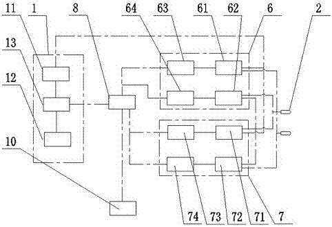
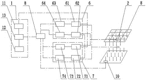
[0045] The invention discloses an indoor static elimination system, as attached image 3 As shown, it includes a number of FFU air outlets 9 arranged on the indoor roof and a number of static state monitors 10, and also includes at least one interlocking high-voltage generating circuit, which is mainly used to selectively generate a For symmetrical electrodes, symmetrical discharge is realized, that is, within a certain period of time, the discharge device in the circuit can simultaneously generate positively charged ions and negatively charged ions.

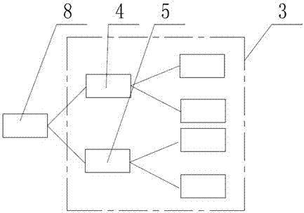
[0046] as attached figure 1 , attached figure 2 As shown, the interlocking high-voltage generating circuit includes a high-voltage power supply 1, an electrostatic discharge unit 2, a high-voltage generating circuit 3 and a main control unit 8;

[0047] The high-voltage power supply 1 includes a positive high-voltage power supply 11 and a negative high-voltage power supply 12. A power adjustment unit 13 is connected between t...

Embodiment 2

[0061] The overall structure of this embodiment is similar to that of Embodiment 1, and the difference is that: the number of the electrostatic discharge units 2 arranged below each of the FFU air outlets 9 is four, and the four electrostatic discharge units 2 are square or Rectangular distribution, they are provided with gaps and the gap distance is adjustable, one of the electrostatic discharge units 2 is connected to each high-voltage loop drive circuit, and two parallel electrostatic discharge units 2 are connected to the first high-voltage generating circuit 3, and the other Two are connected to the second high voltage generating circuit 4;

[0062] At this time, its working process is roughly similar to that of Embodiment 1, the difference being that: when the first high voltage generating circuit 3 is turned on and the second high voltage generating circuit 4 is disconnected, the first high voltage generating circuit 3 connected to the The two electrostatic discharge el...


PUM


Abstract

The invention discloses an interlocking type high-voltage generating circuit and an electrostatic elimination system with the same. The system comprises a high-voltage power source, an electrostatic discharging unit and the high-voltage generating circuit enabling the electrostatic discharging unit to perform symmetric discharge. The high-voltage generating circuit at least comprises a first high-voltage generating unit and a second high-voltage generating unit, wherein the first high-voltage generating unit comprises a first switching circuit which is connected with the high-voltage power source and a master control unit, and the second high-voltage generating unit comprises a second switching circuit which is connected with the high-voltage power source and the master control unit. The electrostatic elimination system is ingenious in design and reasonable in structure, an existing alternating-current boosting transformer technology is abandoned, the frequency is adjustable, the applicability of different acting distances is guaranteed, symmetric electrodes are selectively generated, symmetric discharge is achieved, and meanwhile, positive loads and negative loads are generated. Compared with an alternating-current boosting transformer technology, the transmission speed of the positive load ions and negative load ions can be accelerated, the electrostatic elimination efficiency is improved, and meanwhile, drastic fluctuation of balanced voltage cannot be caused.

Description

technical field [0001] The invention relates to a high-voltage generating circuit and a static elimination system using the circuit, in particular to an interlocking high-voltage generating circuit capable of realizing symmetrical discharge and a static eliminating system using the interlocking high-voltage generating circuit. Background technique [0002] At present, whether it is the electronics industry, the liquid crystal industry or the precision manufacturing industry, higher and higher requirements are put forward for electrostatic protection, which means that anti-static equipment, such as various static eliminators, must continue to improve their performance and have Wider control range, lower participation voltage and faster static elimination time. [0003] The step-up circuit used in the DC static eliminator in the prior art often alternately transforms positive and negative voltages, so that the discharge electrodes generate positively charged ions or negatively...

Claims


Application Information

Patent Timeline
Patent Type & Authority Patents(China)
IPC IPC(8): H05F3/04
Inventor 王荣刚黄成成赵雷
Owner SUZHOU TA&A ULTRA CLEAN TECH CO LTD
Learn More