A method for automatically calibrating the received power of a sensor by a sensor test system

A test system and automatic calibration technology, applied in transmission monitoring/test/fault measurement systems, optical fiber transmission, etc., can solve the problems of low calibration accuracy, complicated operation, and high labor cost, achieve flexible operation, wide application prospects, and improve production. The effect of efficiency

Active Publication Date: 2018-05-08
江西网是科技有限公司
View PDF6 Cites 0 Cited by
  • Summary
  • Abstract
  • Description
  • Claims
  • Application Information

AI Technical Summary

Problems solved by technology

[0005] The purpose of the present invention is to provide a method for automatically calibrating BOB received power by a BOB test system, which mainly solves the problems of complex operation, low calibration accuracy and high labor cost in the calibration method of BOB module received power

Method used


Image

  • A method for automatically calibrating the received power of a sensor by a sensor test system

Examples


Embodiment

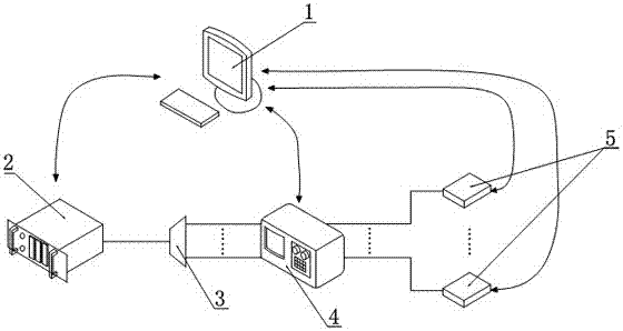
[0043] Such as figure 1 As shown, the present invention provides a BOB module testing system, which includes a host computer 1 , an optical line terminal 2 , an optical splitter 3 , an integrated identification system 4 and a BOB module 5 . The optical line terminal 2, the integrated identification system 4 and the BOB module 5 are all connected to the host computer 1 through the Eth interface. The integrated identification system 4 is integrated with an optical attenuator, and the model of the integrated identification system 4 is preferably IQS-600 or IQS-610, while the model of the integrated optical attenuator is preferably IQS-3150. The optical splitter 3 is simultaneously connected to the optical line terminal 2 and the optical attenuator through an optical fiber, and the BOB module 5 is connected to the optical attenuator through an optical fiber, and in this embodiment, the optical splitter 3 is a 1×8 optical splitter , and there are eight BOB modules 5 and eight opti...


PUM


Abstract

The invention discloses a BOB test system and a method for automatically calibrating BOB receiving power, which solves the problems of complicated operation, high precision and high labor cost in the calibration mode of BOB module receiving power. The present invention includes a host computer, an optical line terminal connected to the host computer, a BOB module and an integrated identification system integrated with an optical attenuator inside, and an optical splitter connected to the optical line terminal and the optical attenuator through an optical fiber at the same time; the optical The attenuator is connected to the BOB module through optical fiber. The invention is reasonable in design and convenient in operation. Through the effective combination of software and hardware, the automatic calibration of BOB receiving power is realized, which not only has a high degree of automation, but also has high calibration accuracy, and effectively reduces unnecessary labor cost input. Therefore, this invention The invention has high application value.

Description

technical field [0001] The present invention relates to a BOSA on board (BOB On Board, BOB for short) technology, in particular to a method for automatically calibrating BOB receiving power by a BOB testing system. Background technique [0002] Although the network has fully popularized the public, ADSL technology is still the mainstream. With the continuous expansion of the scope of network use, users have higher and higher requirements for the network, and with the reduction of the production cost of optical fiber cables, both the majority of users, equipment manufacturers and operators have all set their sights on optical fiber network access. into technology. [0003] However, the high price of optical fiber access network equipment has always been the key and difficult problem for the popularization of fiber-to-the-home. Therefore, finding a low-cost technical equipment that can be produced and used has become the focus of current access network research technology. B...

Claims


Application Information

Patent Timeline
Patent Type & Authority Patents(China)
IPC IPC(8): H04B10/07H04B10/25
Inventor 张春雄
Owner 江西网是科技有限公司
Why Eureka
Try Eureka