Large-caliber rotationally symmetric non-imaging free-form surface reflector and design method thereof

A curved mirror, rotationally symmetric technology, applied in the direction of condensing mirror, optics, instruments, etc., can solve the problems of affecting the uniformity of the solar reflective surface light spot, difficult to obtain high-precision surface shape, etc., to achieve high precision and simplified processing technology. Effect

Active Publication Date: 2015-09-09
SUNCORE PHOTOVOLTAIC TECH
View PDF4 Cites 13 Cited by
  • Summary
  • Abstract
  • Description
  • Claims
  • Application Information

AI Technical Summary

Problems solved by technology

As in the above situation, the surface design is calculated point by point by drawing a grid, which cannot be expressed by an analytical formula. The processing of a series of asymmetrically distributed three-dimensional coordinate point distribution of the mirror surface is a challenge, especially for large It is difficult to obtain a high-precision surface shape for the aperture reflector if it is to be molded at one time, which also affects the uniformity of the solar reflective surface spot

Method used


Image

  • Large-caliber rotationally symmetric non-imaging free-form surface reflector and design method thereof
  • Large-caliber rotationally symmetric non-imaging free-form surface reflector and design method thereof
  • Large-caliber rotationally symmetric non-imaging free-form surface reflector and design method thereof

Examples


Embodiment 1

[0058] A large-aperture rotationally symmetrical non-imaging free-form surface reflector of the present invention and a design method thereof, the specific steps are:

[0059] 1. Design curve

[0060] Ray Equal Projection

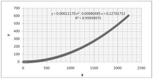
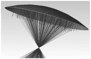
[0061] Suppose a beam of parallel light is incident on the reflective mirror surface, after being reflected by the reflective surface, the outgoing light is distributed on the receiving surface in equal proportions according to the projected radial length, as shown in the attached figure 1 shown. The incident light irradiates the Cn-1 and Cn points of the reflector, and the coordinates in the x direction are xn-1 and xn respectively. They are x'n-1 and x'n respectively, the mirror size is known to be L, and the spot size is D, according to the ratio distribution:

[0062] L D = C n - 1 R ...

Embodiment 2

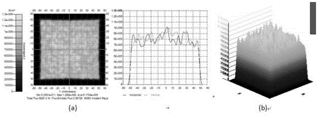
[0091] Import the free-form surface mirror obtained under the given conditions in Example 1 into the ray tracing software for optical simulation, simulate and calculate 1 million rays, and the irradiance diagram on the receiving surface is as follows Figure 5 As shown, (a) is a two-dimensional irradiance map, and (b) is a three-dimensional irradiance distribution map. It can be clearly seen from the figure that in the range of 100×100mm, the light irradiance distribution is quite uniform , the minimum irradiance is 68w / cm 2 , the average irradiance is 100w / cm 2 . The ratio of the minimum irradiance to the average irradiance in the interval is used as the criterion for judging the uniformity of the light spot. Therefore, the final uniformity of the design of the present invention is 80.9%. Regardless of the loss of reflective layer material, the optical efficiency of the receiving surface can reach 98.7%.

Embodiment 3

[0093] The acceptance angle analysis of the free-form reflector surface obtained under the given conditions in Example 1 shows that when the incident light is shifted, the light effect is also reduced. The relationship between the two is as follows Figure 6 shown. When the light effect is reduced to 90% of the light effect of 0°, the incident light angle at this time is the acceptance angle, and the designed acceptance angle is 0.41°. When the incident angle shifts, the light efficiency decreases, and the light intensity distribution on the receiving surface also changes accordingly. Figure 7 , Figure 8 , Figure 9 , Figure 10 Shown are the corresponding spot irradiance distribution diagrams when the incident angles are 0°, 0.2°, 0.4°, and 0.6°, respectively.


PUM


Abstract

The invention discloses a large-caliber rotationally symmetric non-imaging free-form surface reflector and a design method thereof, and belongs to the field of concentrating photovoltaic power generation. Through a light spot which needs to be obtained, is uniformly reflected onto a receiving surface and fully adapts to the shape of the receiving surface, based on a non-imaging reflector principle, firstly a two-dimensional curve is designed and obtained, then quadratic term fitting is performed to the two-dimensional curve by adopting a mathematic modeling method to obtain an equation, the equation is used as a generatrix equation, the generatrix equation is rotated symmetrically to obtain a free-form surface and the free-form surface is the surface pattern of the non-imaging free-form surface reflector. The large-caliber rotationally symmetric non-imaging free-form surface reflector and the design method thereof have the advantages that not only can the uniform light spot be obtained, but also the large-caliber reflector manufacturing process can be simplified to achieve a high-accuracy surface pattern, the light irradiance is uniform and the light-electricity conversion efficiency is improved.

Description

technical field [0001] The invention belongs to the technical field of concentrating photovoltaic power generation, and more specifically relates to a large-diameter rotationally symmetrical non-imaging free-form surface reflector and a design method thereof. Background technique [0002] The use of renewable energy has become a new goal of human exploration. Solar energy is the most common renewable energy, and there are various ways to utilize solar energy, and reflective concentrated photovoltaic power generation system is one of them. The manufacturing process of the reflectors that play the role of concentrating light is one of the important factors that restrict the efficiency of concentrating photovoltaic power generation systems. [0003] The most common designs for concentrating mirrors today are quadric point-focusing mirror designs: parabolic and spherical. In principle, these two types of mirror surfaces can obtain a uniform spot through proper defocusing. Amon...

Claims


Application Information

Patent Timeline
Patent Type & Authority Applications(China)
IPC IPC(8): G02B19/00G02B27/00
CPCG02B27/0012
Inventor 黄启禄
Owner SUNCORE PHOTOVOLTAIC TECH
Why Eureka
Try Eureka