
Rotary stamping compressed rotor plane cascade experimental system

Active Publication Date: 2015-09-09
DALIAN MARITIME UNIVERSITY
View PDF6 Cites 32 Cited by
  • Summary
  • Abstract
  • Description
  • Claims
  • Application Information

AI Technical Summary

Problems solved by technology

Due to the high working speed, the rotary stamping compression rotor test piece has very strict requirements on materials, lubrication and support. Therefore, the research and development of the rotary stamping compression rotor level test system and the test research have long development cycle, high technical difficulty and risk. At the same time, the test of the rotary stamping compression rotor stage can only obtain the total parameters of the inlet and outlet and the pressure distribution parameters of the casing wall, but cannot obtain the more detailed flow field structure parameters inside it, which is not conducive to a deep understanding of the rotary stamping compression rotor internal flow mechanism
The existing compressor flat cascade experiment system is aimed at conventional compressors. Although there are many measurement methods, the incoming flow velocity in the experimental section is relatively low, mostly subsonic or transonic, which cannot meet the needs of rotating, stamping and compressing rotor flat cascades. The requirement that the incoming flow velocity in the experimental section is higher supersonic velocity
In addition, the outlet of the experimental section of the existing compressor plane cascade experimental system is directly connected to the atmospheric environment, and there is no throttle valve and other equipment, so the adjustment of the back pressure at the outlet of the experimental section cannot be realized.
In addition, in order to obtain the internal flow characteristics and overall performance of the rotary stamping compression rotor with the variation law of the experimental conditions, it is necessary to carry out experimental research on the rotary stamping compression rotor plane cascade under multiple working conditions, and there is no special research on the rotary stamping compression rotor at present. Experimental system for multi-working condition research on planar cascades

Method used


Image

  • Rotary stamping compressed rotor plane cascade experimental system
  • Rotary stamping compressed rotor plane cascade experimental system
  • Rotary stamping compressed rotor plane cascade experimental system

Examples


Embodiment Construction

[0029] The present invention is described in further detail below in conjunction with accompanying drawing:

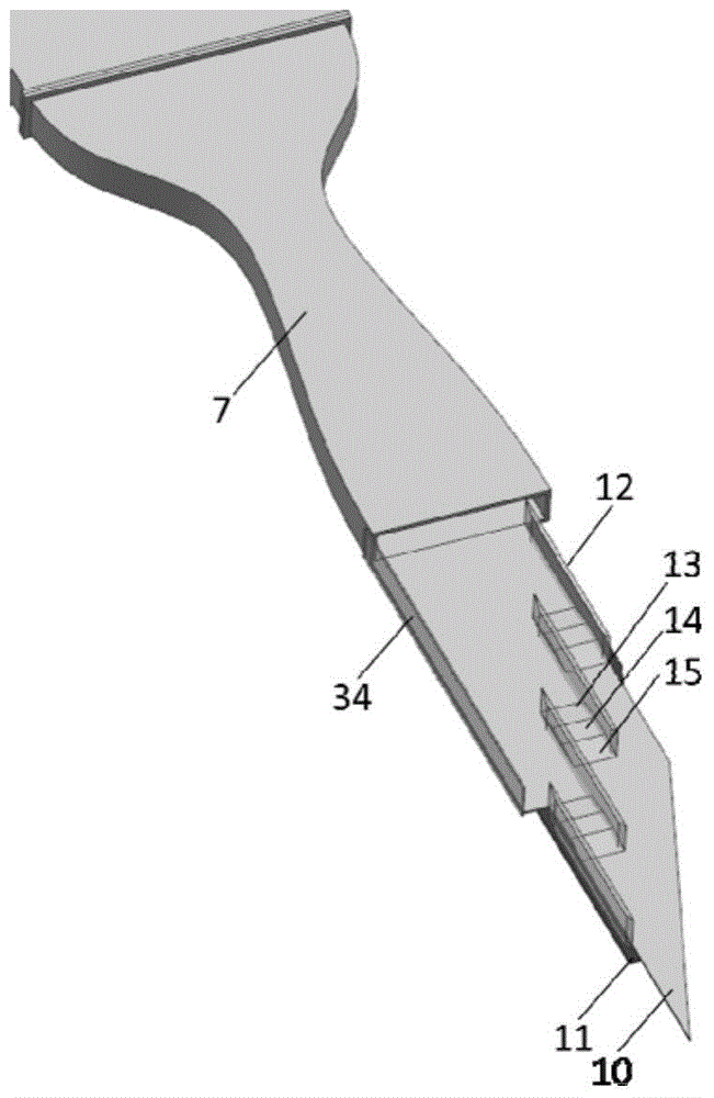
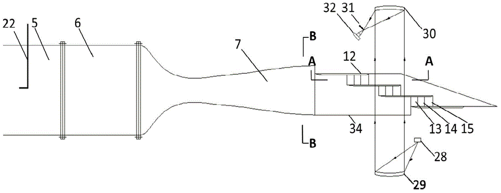
[0030] Such as figure 1 As shown, the rotary stamping compression rotor planar cascade experimental system of the present invention is mainly composed of five parts: air source supply, wind tunnel shell, Laval nozzle 7, planar cascade experimental section 8, and experimental testing and data acquisition system. The motor 1 is controlled by the frequency conversion controller, and the centrifugal blower 2 is driven to provide a continuous air source, thereby obtaining a certain total pressure and speed of the air source. This part of the air flow passes through the pressure stabilization section 3 and enters the diffuser section 4 of the wind tunnel shell. The static pressure value in the circular to square diffuser section is improved, and after entering the square steady flow section 5, due to the vortex breaking and rectification effect of the built-in honeycomb and ...


PUM


Abstract

The invention discloses a rotary stamping compressed rotor plane cascade experimental system comprising an air supply system, a wind tunnel barrel, a Laval nozzle, a plane cascade experimental section, and an experimental test and data acquisition system. The plane cascade experimental section is composed of an upper cover plate, a lower end wall, a lower support plate, partition plates, a compression surface, a throat, a pressure expansion surface, a throttle valve, a throttle valve motor, a throttle valve frequency converter, and a rotatable platform. The plane cascade experimental section is provided with an odd number of air inlet flow paths which are partitioned by an even number of partition plates. The Laval nozzle is arranged before the plane cascade experimental section, high supersonic flow is achieved with low cost and low technical difficulty, and the inlet flow Mach number can be adjusted by replacing the Laval nozzle, so that rotary stamping compressed rotor plane cascade experimental study under different flow Mach numbers is realized. Moreover, rotary stamping compressed rotor plane cascade experimental study under different back pressures, different flow angles of attack and different partition top gaps can be carried out.

Description

technical field [0001] The invention relates to the field of gas turbines, in particular to an experimental system for rotating, stamping and compressing rotor plane cascades. Background technique [0002] Gas turbine is a new type of power device that has developed rapidly in recent decades after steam turbine and internal combustion engine. After it has gained a dominant position in the field of aeroengines, it is increasingly used in surface ships, gas turbine power plants and other fields. The gas turbine is based on component technology, and the improvement of its performance is inseparable from the development of component technology. The compressor is one of the three core components of the gas turbine, and its technological innovation plays a decisive role in improving the performance of the gas turbine. [0003] As a new type of supersonic compressor rotor, the rotary stamping compression rotor has the advantages of high single-stage pressure ratio, compact structu...

Claims


Application Information

Patent Timeline
Patent Type & Authority Applications(China)
IPC IPC(8): G01M15/14G01M15/02
Inventor 韩吉昂钟兢军管健杨凌苑辰光
Owner DALIAN MARITIME UNIVERSITY
Learn More