
A new optical arm amplified high-precision length sensor and its measuring method

A technology of length sensor and measurement method, which is applied in the direction of measuring devices, instruments, optical devices, etc., and can solve problems such as difficulty in improving measurement accuracy

Active Publication Date: 2018-06-01
张白
View PDF10 Cites 0 Cited by
  • Summary
  • Abstract
  • Description
  • Claims
  • Application Information

AI Technical Summary

Problems solved by technology

[0004] Due to the limitation of the physical structure of the photolithography process, it is difficult to improve the measurement accuracy of the grating sensor, which cannot meet the needs of higher and higher measurement accuracy. It is urgent to develop a sensor with a simple structure and higher precision.

Method used


Image

  • A new optical arm amplified high-precision length sensor and its measuring method
  • A new optical arm amplified high-precision length sensor and its measuring method
  • A new optical arm amplified high-precision length sensor and its measuring method

Examples


Embodiment 1

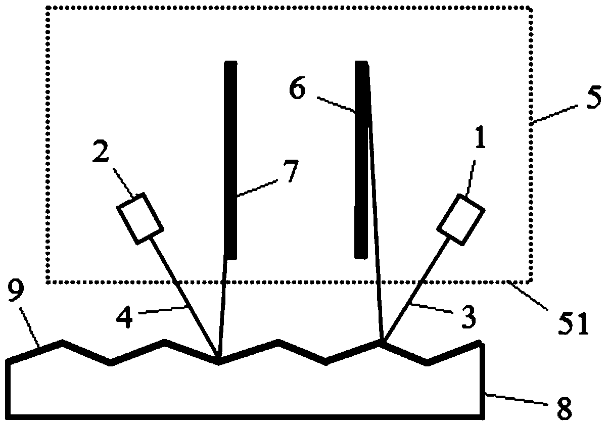
[0065] Such as Figure 1-7 As shown, a new optical arm amplified high-precision length sensor, including:

[0066] Laser beam one 3, laser beam two 4;

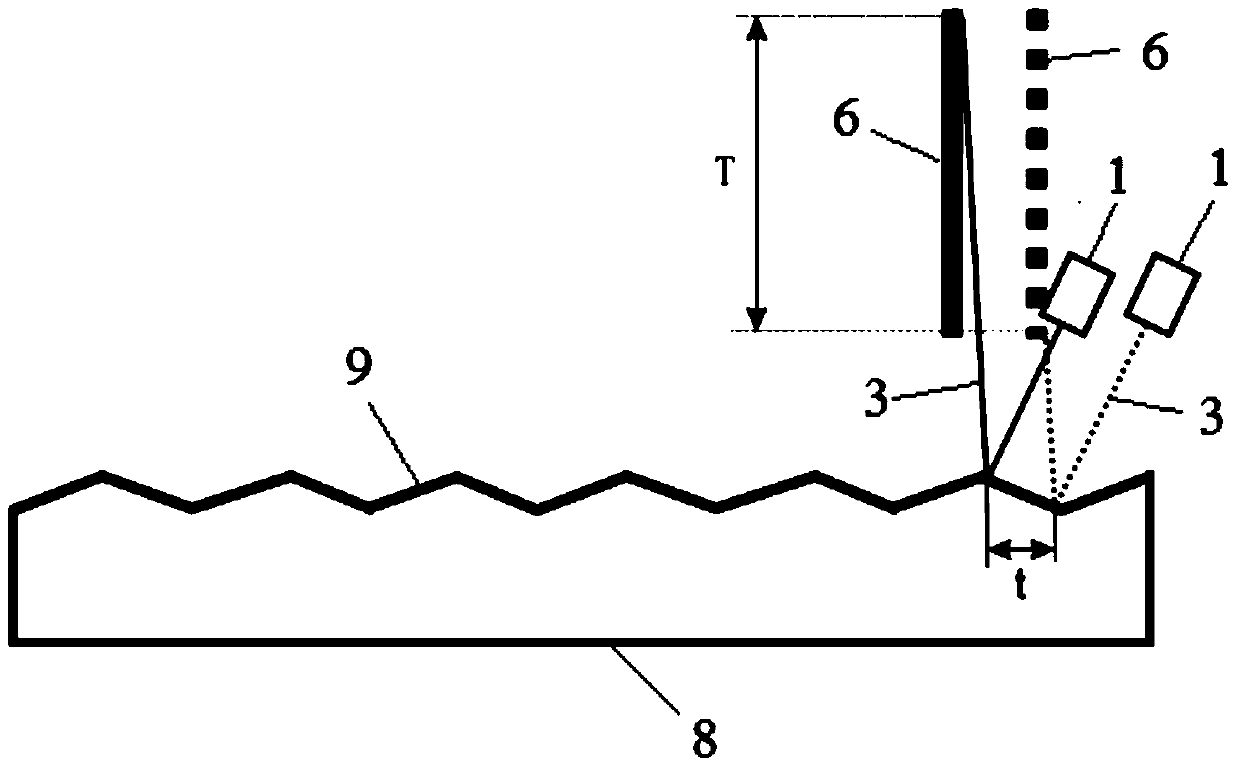
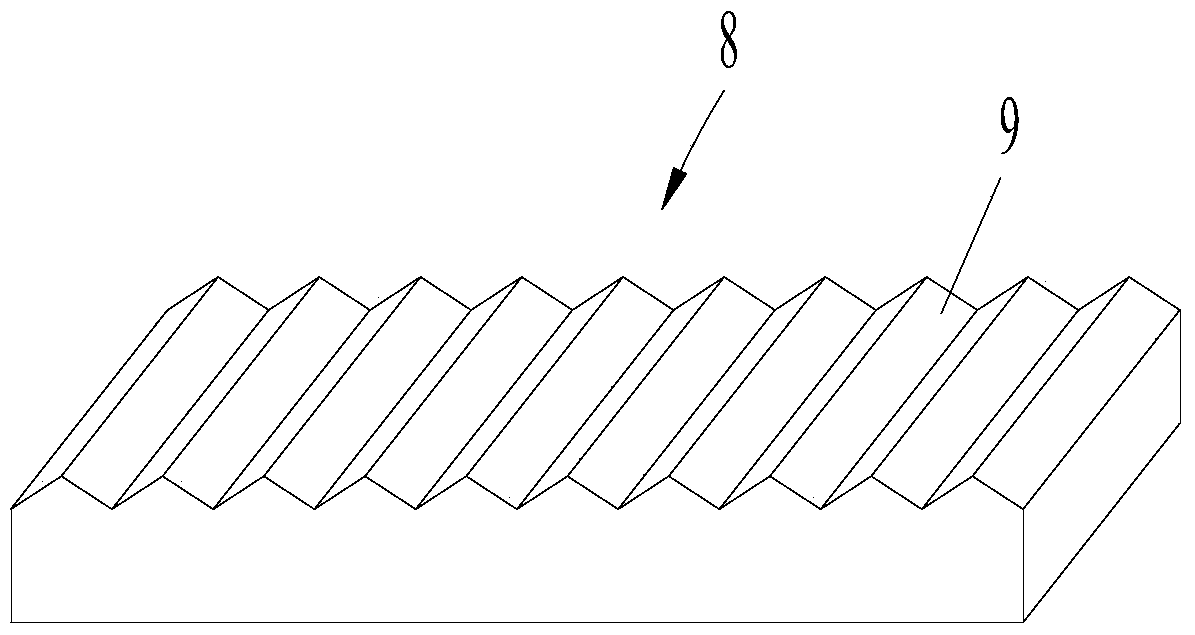
[0067] The reflective part 8 is provided with several reflective surfaces 9 for reflecting the laser beam one 3 and the laser beam two 4 on the reflective part 8, each reflective surface 9 has a symmetrical convex shape in section, and all the reflective surfaces 9 are connected end to end to form reflector array;

[0068] A photodetector 6 is used to receive the laser beam reflected by the reflective surface 9 of the reflective component 8 and display the reflected position of the laser beam 3;

[0069] The photodetector 2 7 is used to receive the laser beam reflected by the laser beam 2 4 on the reflective surface 9 in the reflective component 8 and display its reflection position;

[0070] The processing system calculates the displacement change of the measured object according to the change value of the reflection posit...

Embodiment 2

[0077] Such as Figure 6 As shown, a novel optical arm amplified high-precision length sensor measurement method includes the novel optical arm amplified high-precision length sensor as in Embodiment 1, and its measurement method includes the following steps:

[0078] Step 1. Fix the measured object on the reflective part 8 or the reading head 5, wherein the reflective surface 9 is adjusted to be consistent with the moving direction of the measured object, wherein the reflective part 8 is provided with an installation for easy fixing on the measured object hole or paste;

[0079] Step 2, adjust the positional relationship of laser beam 1 3, laser beam 2 4, reflector 8, photodetector 1 6, photodetector 2 7, make them mutually adaptable, make laser beam 1 3, laser beam 2 4 in The two laser beams reflected on the reflection member 8 can be detected by the photodetector one 6 and the photodetector two 7 respectively; and adjust the photodetector one 6, photodetector two 7 and the...

Embodiment 3

[0098] When the displacement value of the object to be measured is less than the reflection length of one of the reflection unit surfaces of a reflection surface 9 on the reflection component 8, the processing system does not need to switch and superimpose the two laser beams and photodetectors, and only needs to adopt the embodiment The laser beam 1 3 and the photodetector 1 6 in 2, or the laser beam 2 4 and the photodetector 2 7, cooperate with the reflection component 8 to measure the displacement of the measured object.

[0099] This embodiment is suitable for measuring one-time displacement of the measured object, or continuous incremental displacement values, and the continuous incremental displacement values ​​are all smaller than the reflection length of one of the reflection unit surfaces of each reflection surface 9 .


PUM


Abstract

The invention discloses a novel light-arm-amplification type high-precision length sensor and a measurement method thereof. The length sensor comprises a laser beam I, a laser beam II, a reflection component, a photoelectric detector I, a photoelectric detector II, and a processing system. To be specific, the reflection component is provided with a plurality of reflection surfaces for reflecting the laser beam I and the laser beam II; the cross section of each reflections surface is in a protruding shape; and all reflection surfaces are connected in an end-to-end mode to form a reflection surface array. The photoelectric detector I is used for receiving a laser beam after reflection of the laser beam I by the reflection component and displaying the reflection position; and the photoelectric detector II is used for receiving a laser beam after reflection of the laser beam II by the reflection component and displaying the reflection position. The processing system carried out processing according to the position changing value, received by the photoelectric detector I, of the laser beam I and the position changing value, received by the photoelectric detector II, of the laser beam II, thereby obtaining a displacement value of the measured object. The provided sensor having a simple structure is suitable for measurement of continuous changes of displacements of the measured object and has advantages of high reliability and precision and easy batch production.

Description

technical field [0001] The invention relates to the field of precision testing technology and instruments, in particular to a novel optical arm amplified high-precision length sensor and a measuring method. Background technique [0002] Displacement sensor is a commonly used geometric quantity sensor, which is widely used in many fields such as aerospace, industrial production, machinery manufacturing and military science. There are many ways to measure displacement. Smaller displacements (such as less than 1cm) are usually detected by strain gauges, inductances, differential transformers, eddy currents, and Hall sensors. Larger displacements (such as greater than 1cm) are usually detected by induction synchronization. Sensors, gratings, capacitive grids, magnetic grids and other sensing technologies to measure. Among them, the grating sensor has the advantages of easy digitalization, high precision (currently the highest resolution can reach the nanometer level), strong an...

Claims


Application Information

Patent Timeline
Patent Type & Authority Patents(China)
IPC IPC(8): G01B11/02
Inventor 张白丁子兮
Owner 张白
Learn More