
Steel wire rope connecting snap

A technology of steel wire rope and buckle, which is applied in the direction of transmission elements or pulley ropes or cables, textile cables, protective equipment, etc., and can solve problems such as inability to play a protective role, complex structure, and unfavorable processing.

Inactive Publication Date: 2015-09-09
ZUNYI CHONGYUE METAL PROD CO LTD
View PDF1 Cites 3 Cited by
  • Summary
  • Abstract
  • Description
  • Claims
  • Application Information

AI Technical Summary

Problems solved by technology

[0003] In the early installation technology of wire rope mesh, electric welding is usually used to fix the intersection joints of wire ropes. The obvious defect of this method is that the welding process will change the mechanical properties of the welding points of the wire ropes, and the welding points are easy to break, which will lead to the failure of the wire ropes. There are loopholes in the network, which cannot play the role of protection
[0004] Along with the improvement of technology, the fixed mode of the intersection node of wire rope net is improved to some extent at present, as the technology adopted in the patent of CN101105025A of Chinese Patent Publication No. is to use cross-shaped buckle to fix at the intersection node of wire rope, this technology includes upper card, The lower card and multiple claws, when in use, use the claw tool to press the claws on the upper card and the lower card to fix the intersection node of the wire rope, because the fastening force is mainly generated by the claw acting on the wire rope , the force of the claws is small, so it is necessary to set multiple claws at the bottom of the upper and lower cards. During production and processing, it is necessary to process multiple claws on the upper and lower cards. The structure is complex, which is not conducive to processing and improves production efficiency. low

Method used


Image

  • Steel wire rope connecting snap
  • Steel wire rope connecting snap
  • Steel wire rope connecting snap

Examples


Embodiment 1

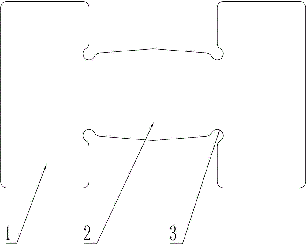
[0020] Embodiment 1: as figure 1 As shown, it includes connecting plate 2 and wing plate 1 combined in an "H" shape. The connecting plate 2 and wing plate 1 are integrally formed and the materials are all iron blocks. The wing plate 1 is arranged at both ends of the connecting plate 2. The wing plate 1 The width equals the circumference of steel wire rope, makes wing plate 1 just can wrap steel wire rope one circle. Such as figure 2 As shown, the connecting plate 2 is a circular arc plate that can fit on the surface of the steel wire rope. The arc of the connecting plate 2 is determined by the thickness of the steel wire rope, so that it can just wrap the steel wire rope in the circumferential direction, and the steel wire rope can be stuck in it when in use. . The inner surface of the connecting plate 2 is provided with convex teeth 4 to increase the friction between the connecting plate 2 and the steel wire and reduce the possibility of the steel wire rope sliding. The an...

Embodiment 2

[0022] Embodiment 2: In addition to being able to combine the connecting plate 2 and the wing plate 1 to form an "H" shape, it can also be deformed, such as Figure 4 As shown, in the shape of "n", the fastening function of the present invention can also be realized.

Embodiment 3

[0023] Embodiment 3: Except that connecting plate 2 and wing plate 1 can be combined into "H" shape and "n" shape, it can also be deformed, such as Figure 5 As shown, it is in the shape of "Z", which can also realize the fastening function of the present invention.

[0024] The present invention is simple in structure, easy to manufacture, and convenient to use. Two steel wire ropes with the same shape and size are used in conjunction with buckles, and the cross joints of the steel wire ropes are wrapped and pressed through the wing plate 1 and the connecting plate 2, and the force is large. It effectively prevents the sliding of the joints and achieves the purpose of fastening the steel wire mesh; after the fastening, the cross joints are tightly wrapped and closed by the buckle, which reduces the infiltration of external rainwater and can better prevent the inner layer of the buckle and the connection between the wire rope The steel wire is oxidized and corroded.


PUM


Abstract

The invention relates to a fastening device for steel wire rope cross joints and particularly relates to a steel wire rope connecting snap. The snap comprises a connection plate and a wing plate which are combined into an I shape, the wing plate is connected with the two ends of the connection plate, and the width of the wing plate is not smaller than the perimeter of the steel wire rope. The snap is simple in structure, easy to manufacture and convenient to use. Two steel wire rope connecting snaps which are completely identical in shape and size are used in a fit mode, the steel wire rope cross joint is covered and compressed through the wing plates and the connection plates, the acting force is large, node sliding is prevented effectively, and accordingly, steel wire gauzes are fastened.

Description

technical field [0001] The invention relates to fastening equipment for the intersection nodes of steel wire rope nets, in particular to buckles for connecting steel wire ropes. Background technique [0002] On both sides of mountain roads and railways, there are often landslides, mudslides, collapses, and rockfalls on the side of the road, which seriously affect traffic safety and smooth roads, and sometimes even threaten the safety of passing vehicles and pedestrians. Therefore, in order to prevent falling rocks from affecting the normal operation of the road, and to ensure the safety of people and property, protective nets are often installed on the slope walls on both sides of the road to intercept the falling mud, rocks and sand. In recent years, as a scientific, practical and environmentally friendly engineering technology, flexible protective wire rope nets have been widely used in rockfall protection projects. [0003] In the early installation technology of wire ro...

Claims


Application Information

Patent Timeline
IPC IPC(8): F16G11/02E01F7/04
CPCF16G11/02E01F7/04
Inventor 田阜泽
Owner ZUNYI CHONGYUE METAL PROD CO LTD
Learn More