Air compressor with ultrasonic bearings

An air compressor and ultrasonic technology, which is applied to the components of pumping devices for elastic fluids, mechanical equipment, machines/engines, etc. Low problems, to achieve the effect of good control of gas film formation, improved bearing capacity, and high product speed

Inactive Publication Date: 2015-09-09
HUNAN UNIV +1
View PDF6 Cites 12 Cited by
  • Summary
  • Abstract
  • Description
  • Claims
  • Application Information

AI Technical Summary

Problems solved by technology

[0003] The air compressor of the fuel cell uses a motor to drive the shaft to rotate, and drives the impeller to generate a boost that acts on the intake manifold of the fuel cell to increase the intake air volume and pressure of the fuel cell and improve the efficiency of the fuel cell. The working process also consumes power, which is about 20% of the battery output. Therefore, considering the efficiency of the battery stack, in order to obtain the overall performance, it is necessary to find the most effective compression method
[0004] At present, air compressor bearings usually use rolling bearings and sliding bearings, which have the following problems: First, due to the use of lubricating oil, oil leakage will inevitably occur, and there will be leakage of lubricating oil through the oil seal and cause intercooler Second, due to the existence of friction, the rotor speed is low and the efficiency is low; and the bearing life will be shortened due to wear

Method used


Image

  • Air compressor with ultrasonic bearings
  • Air compressor with ultrasonic bearings
  • Air compressor with ultrasonic bearings

Examples


Embodiment Construction

[0034] The present invention will be described in detail below in conjunction with the accompanying drawings and specific embodiments. This embodiment is carried out on the premise of the technical solution of the present invention, and detailed implementation and specific operation process are given, but the protection scope of the present invention is not limited to the following embodiments.

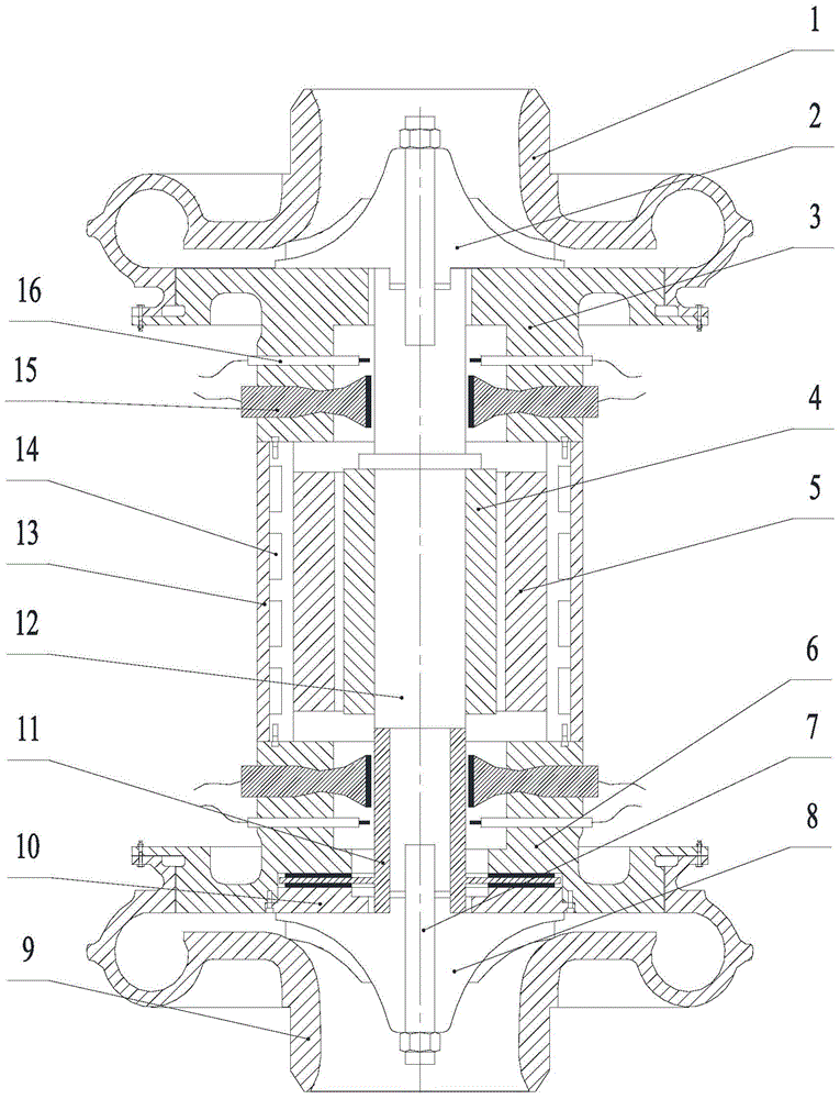
[0035] Such as figure 1 As shown, an air compressor using an ultrasonic bearing consists of a housing 13, a motor stator 5, a motor rotor 4, a rotor shaft 12, an ultrasonic bearing, a spiral groove thrust bearing 11, a first bearing sleeve 3, and a second bearing sleeve 6 , the first impeller 2, the second impeller 8, the first impeller shell 1, the second impeller shell 9 and the thrust bearing cover 10, etc. The specific connection method is:

[0036] The housing 13, the motor stator 5, the motor rotor 4 and the rotor shaft 12 are sequentially arranged from the inside to the outsid...


PUM


Abstract

The invention relates to an air compressor with ultrasonic bearings. The air compressor with ultrasonic bearings comprises a shell, a motor stator, a motor rotor and a rotor shaft from outside to inside, and further comprises the ultrasonic bearings and a spiral groove type thrust bearing, wherein bearing bushes are arranged at the two ends of the shell, impellers are arranged at the two ends of the rotor shaft respectively, the impellers are sleeved with impeller shells, the impeller shells are in sealing connection with the bearing bushes and are provided with air inlets and air outlets, the air outlet of the impeller shell at one end is connected with the air inlet of the impeller shell at the other end, the ultrasonic bearings are arranged on the bearing bushes at the two ends and are in noncontact connection with the rotor shaft, the spiral groove type thrust bearing is arranged on the part, between the bearing bush at one end and the impeller at the same end, of the rotor shaft, and a thrust bearing cap is arranged between the spiral groove type thrust bearing and the corresponding impeller. Compared with the prior art, the air compressor with ultrasonic bearings has the advantages of being high in rotation speed and efficiency, long in service life, free of lubricating oil and the like.

Description

technical field [0001] The invention relates to an air compressor, in particular to an air compressor using an ultrasonic bearing. Background technique [0002] As one of the main directions of new energy development at present, fuel cell technology is an industry that the country needs to focus on in the future, and it can be applied to transportation, backup power generation, etc. A fuel cell is a device that converts hydrogen energy into electrical energy, and its energy conversion efficiency can reach 60% to 80% without generating greenhouse gases. But if the fuel cell wants to obtain high power density and good performance, it must work under higher pressure. Increasing the air supply pressure can increase the energy density of the fuel cell system, so the fuel cell needs a dedicated air supply system to provide high-pressure air to the fuel cell. [0003] The air compressor of the fuel cell uses a motor to drive the shaft to rotate, and drives the impeller to generat...

Claims


Application Information

Patent Timeline
Patent Type & Authority Applications(China)
IPC IPC(8): F04D29/08F04D29/056F04D29/58
Inventor 冯凯邓志洪张智明章桐
Owner HUNAN UNIV
Why Eureka
Try Eureka