Eureka AIR delivers breakthrough ideas for toughest innovation challenges, trusted by R&D personnel around the world.

A wind turbine blade turning device

A technology of wind power blade and turning device, which is applied in the direction of turning objects, transportation and packaging, pile separation, etc., can solve the problems of low turning efficiency, laborious operation, and inability to ensure blade torque, and achieves increasing rotational torque and reducing driving force. , weight reliable effect

Active Publication Date: 2018-03-16
上海中帧机器人控制技术发展有限公司
View PDF8 Cites 2 Cited by
  • Summary
  • Abstract
  • Description
  • Claims
  • Application Information

AI Technical Summary

Problems solved by technology

[0004] However, since the wind turbine blade turning device with the above structure uses a U-shaped bracket as a clamping part to clamp the wind turbine blade, there is no force applying mechanism for clamping the wind turbine blade, so it is difficult to ensure the reliability of the wind turbine blade with large volume and mass. holding
Moreover, using the handwheel to manually drive the rollers to turn over is not only laborious to operate, but also inefficient to turn over
In addition, it is difficult to ensure the effective clamping of the wind turbine blades due to the force application measures without clamping, and it is difficult to ensure the stability of the overturn; the use of friction drive cannot ensure sufficient torque for the blades

Method used


Image

  • A wind turbine blade turning device
  • A wind turbine blade turning device
  • A wind turbine blade turning device

Examples


Embodiment Construction

[0022] In order to make the technical means, creative features, goals and effects of the present invention easy to understand, the following embodiments will specifically illustrate the wind turbine blade turning device provided by the present invention in conjunction with the accompanying drawings.

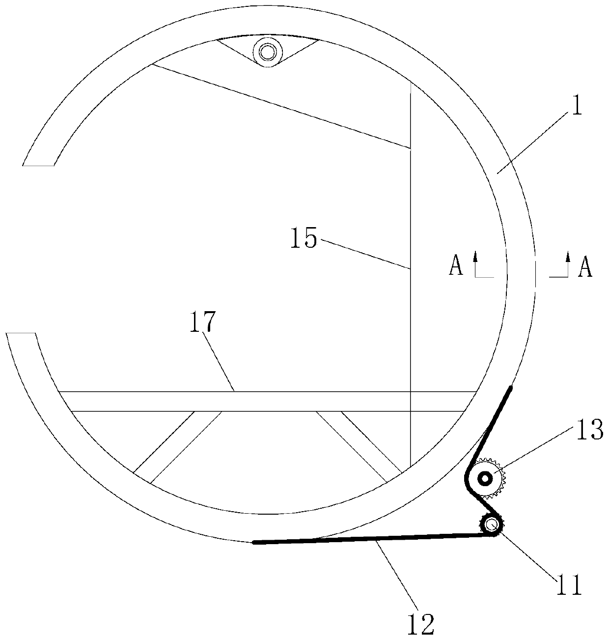
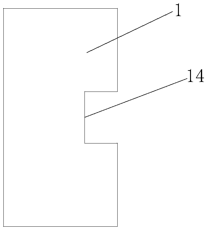
[0023] Such as figure 1 As shown, the wind turbine blade turning device provided in this embodiment includes: a swivel 1, a clamping mechanism, a supporting base 2, and a driving mechanism.

[0024] Specifically, the clamping mechanism is installed in the swivel 1 and turns over synchronously with the swivel 1 . In this embodiment, the clamping mechanism includes a fixed clamp arm 3 , a movable clamp arm 4 matching the fixed clamp arm 3 , and a link assembly for driving the movable clamp arm 4 to deflect. Wherein, the fixed clamping arm 3 has a first clamping surface 31, the movable clamping arm 4 is an L-shaped structure and has a second clamping surface 41 facing the first cla...


PUM


Abstract

The invention discloses a turning device for wind power blades, which is characterized in that it comprises: a swivel ring provided with a gap; a clamping mechanism installed in the swivel ring and flipped synchronously with the swivel ring; a supporting base; And a driving mechanism, including a power part, a chain drive part connecting the power part and the swivel; wherein, the clamping mechanism includes a fixed clamp arm, a movable clamp arm matched with the fixed clamp arm, and a link assembly that drives the deflection of the movable clamp arm; the fixed clamp arm has a first clamping surface, the movable clamp arm has a second clamping surface facing the first clamping surface, and the The clamping area of ​​the wind turbine blade is formed between the first clamping surface and the second clamping surface, and the notch faces the clamping area; the wind turbine blade turning device has the advantages of simple structure and large rotational torque, so that The flipping of wind turbine blades is more efficient, safe and reliable.

Description

technical field [0001] The invention relates to a wind power generator, in particular to a wind power blade turning device. Background technique [0002] A wind turbine is a power machine that converts clean, non-polluting wind energy into mechanical energy. As far as its working principle is concerned, the wind turbine uses the wind to blow the blades to rotate, and then increases the rotation speed through the speed increaser to drive the engine. generate electricity. Wind power blades are one of the core components of wind power generators, and the enlargement of wind power generators is a trend in the utilization of wind energy in the world. With the gradual increase in the capacity of wind power generators, the length of wind power blades is also increasing. The longer it is, the more complicated the corresponding blade manufacturing process is. In the production process of wind power blades, it needs to go through processes such as grinding and painting, and it also ...

Claims


Application Information

Patent Timeline
Patent Type & Authority Patents(China)
IPC IPC(8): B65H15/00
Inventor 乌建中
Owner 上海中帧机器人控制技术发展有限公司
Why Eureka
Eureka Blog
Learn More