Automatic single plate feeding machine

A plate feeding machine, automatic technology, applied in the direction of object supply, pile separation, thin material processing, etc., can solve the problems of high labor intensity, high labor cost, and high production cost of operators, and achieve low labor intensity and low labor cost. , the effect of high work efficiency

Active Publication Date: 2015-09-09
SHANDONG BAISHENGYUAN GRP
View PDF6 Cites 3 Cited by
  • Summary
  • Abstract
  • Description
  • Claims
  • Application Information

AI Technical Summary

Problems solved by technology

[0002] At present, due to the rough surface of the existing veneer after rotary cutting, in order to improve the smoothness of both sides of the veneer, it needs to be polished with a sander. Stack on the lifting platform, then lift the lifting platform to the sand sawing production line with an aerial crane, manually push a single veneer to the roller conveyor line, and then transport the veneer to the sander or sawing machine through the roller conveyor line For processing, the disadvantage is: due to the large area of ​​the veneer, at least two people are required to move the veneer to the roller conveyor line at the feeding end of the roller conveyor line when pushing. The substantial disadvantage is: high labor cost , high production cost, low work efficiency, and high labor intensity for operators

Method used


Image

  • Automatic single plate feeding machine
  • Automatic single plate feeding machine
  • Automatic single plate feeding machine

Examples


Embodiment Construction

[0014] Below in conjunction with accompanying drawing, the present invention is further described:

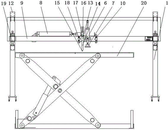
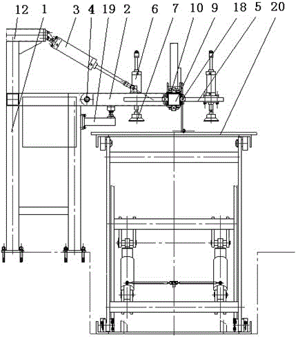
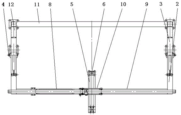
[0015] As shown in the accompanying drawings, a veneer automatic board feeding machine is characterized in that it includes a fixed frame, a turning rod 2, a control system, a turning cylinder 3, a rotating shaft 4, a suction cup bracket 5, a lifting cylinder 6, a vacuum suction cup 7, and a moving cylinder 8. Fix the guide rail frame 9 and the sliding sleeve 10. The fixed frame is composed of the outrigger frame 1 and the connecting rod 11. One side of the two outrigger frames 1 is fixedly connected by the connecting rod 11, and the two ends of the other side are respectively connected by the rotating shaft 4. Hinged with the overturning rod 2, the top of the leg frame 1 is provided with a overturning cylinder 3, one end of the overturning cylinder 3 is connected to the connecting rod 11 through the support frame 12, and the other end is connected to the overturning bar 2, so t...


PUM


Abstract

The invention discloses an automatic single plate feeding machine which is characterized by comprising a fixing framework, a turning-over rod, a control system, a turning-over air cylinder, a rotating shaft, sucker supports, a lifting air cylinder, a vacuum sucker, a moving air cylinder, an induction support, contact idler wheels, a contact switch, a fixing guide rail frame and a sliding sleeve. The fixing framework is composed of a supporting leg frame and a connecting rod. One side of the supporting leg frame is connected with the connecting rod. The two ends of the other side of the supporting leg frame are hinged to the turning-over rod. One end of the turning-over air cylinder is connected with the connecting rod, and the other end of the turning-over air cylinder is connected with the turning-over rod. The other end of the turning-over rod is connected with the fixing guide rail frame. The fixing guide rail frame is sleeved with the sliding sleeve in a sliding mode. The moving air cylinder is arranged on the portion, at one side of the sliding sleeve, of the fixing guide rail frame. One end of the moving air cylinder is connected with the fixing guide rail frame, and the other end of the moving air cylinder is connected with the sliding sleeve. The sucker supports are arranged at the two sides of the sliding sleeve respectively. The lifting air cylinder is fixed to the sucker supports. The lower end of the lifting air cylinder is connected with the vacuum sucker. The automatic single plate feeding machine has the advantages of being novel in structure, high in working efficiency, low in labor intensity, high in automation degree, stable in operation and the like.

Description

technical field [0001] The invention relates to the technical field of plate processing production lines, in particular to an automatic veneer feeding machine used in plate processing production lines. Background technique [0002] At present, due to the rough surface of the existing veneer after rotary cutting, in order to improve the smoothness of both sides of the veneer, it needs to be polished with a sander. Stack on the lifting platform, then lift the lifting platform to the sand sawing production line with an aerial crane, manually push a single veneer to the roller conveyor line, and then transport the veneer to the sander or sawing machine through the roller conveyor line For processing, the disadvantage is: due to the large area of ​​the veneer, at least two people are required to move the veneer to the roller conveyor line at the feeding end of the roller conveyor line when pushing. The substantial disadvantage is: high labor cost , high production costs, low wor...

Claims


Application Information

Patent Timeline
Patent Type & Authority Applications(China)
IPC IPC(8): B65H5/10
Inventor 王成瑞宋睿婷邹华敏邹霞祁世飞丛培敏于永鹏邓斌
Owner SHANDONG BAISHENGYUAN GRP
Why Eureka
Try Eureka