
A kind of airtight chicken house ventilation system and air flow organization method

A ventilation system, a closed technology, applied in animal houses, poultry cages or houses, poultry industry, etc., can solve the problems of air flow disorder, large ventilation resistance, increased ventilation resistance, etc., to increase airflow speed and increase ventilation Efficiency, the effect of reducing ventilation resistance

Active Publication Date: 2017-04-19
CHINA AGRI UNIV
View PDF5 Cites 0 Cited by
  • Summary
  • Abstract
  • Description
  • Claims
  • Application Information

AI Technical Summary

Problems solved by technology

So how to better realize the ventilation and cooling efficiency of caged laying hens, no one has conducted relevant research and reports on this at present
2. Large temperature difference between inlet and outlet
3. Uneven air distribution in the house
4. The design of the air inlet is unreasonable, resulting in disordered air flow and large ventilation resistance
However, the airflow between the wet curtain air inlet and the vertical baffle is disordered and unorganized, and the ventilation resistance is significantly increased, resulting in energy waste
5. The front end of the chicken cage blocks the airflow movement, the airflow is disordered, and the ventilation resistance is large
The air inlet of the existing chicken house is slender and horizontally arranged, and the air inlet and the chicken cage are vertically intersected, and the chicken cage blocks the airflow movement, resulting in poor organization of the airflow movement in this section and serious turbulence

Method used


Image

  • A kind of airtight chicken house ventilation system and air flow organization method
  • A kind of airtight chicken house ventilation system and air flow organization method
  • A kind of airtight chicken house ventilation system and air flow organization method

Examples


Embodiment Construction

[0035] The present invention will be further described below in conjunction with the accompanying drawings and embodiments.

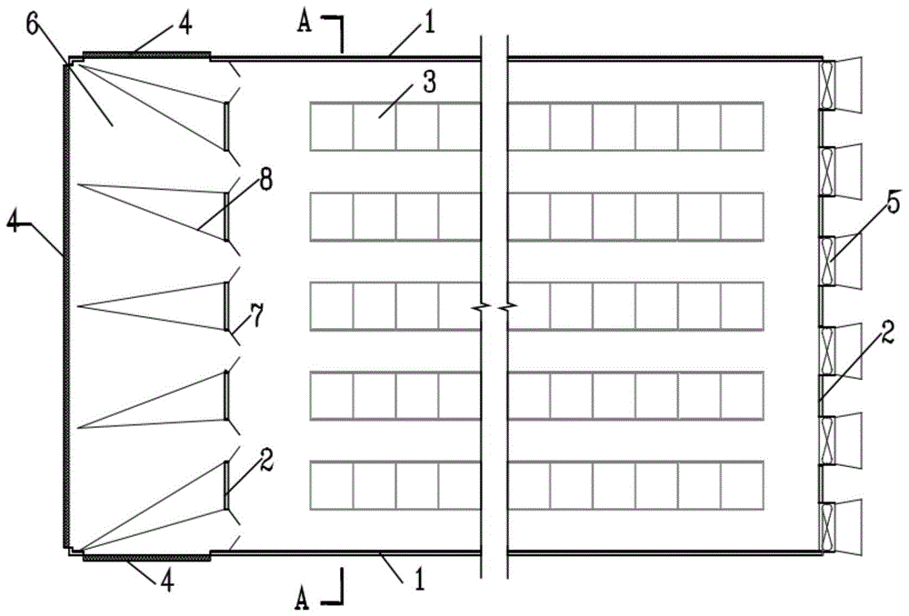
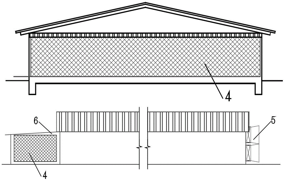
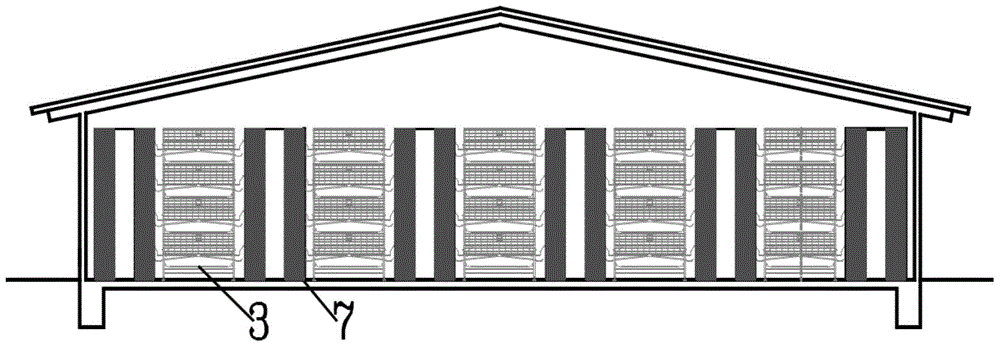
[0036] Such as figure 1 , 2 As shown, the airtight chicken house ventilation system of the present invention includes a vertical wall 1, a gable wall 2, a wet curtain cooling device 4, a negative pressure fan 5, a compartment 6, an air inlet double-fan deflector 7 and a deflector 8.

[0037] Wherein, the chicken cages 3 are arranged in rows along the vertical wall 1, and passages are formed between different rows of chicken cages 3 and between the outermost chicken cages 3 and the vertical wall 1, and the passages form the passage ventilation in the present invention. Negative pressure fan 5 is installed on the gable wall 2 at one end, as the air outlet of the airtight chicken house ventilation system of the present invention. On the outside of the gable 2 at the other end corresponding to it, a compartment 6 is arranged, and a wet curtain cooling dev...


PUM


Abstract

The invention belongs to the field of agriculture facilities, and relates to a closed henhouse ventilating system and an air flow organization method. The system includes a longitudinal wall (1), a mountain wall (2), hen cages (3), a wet curtain cooling device (4) and a blower (5); the hen cages (3) are in parallel to the longitudinal wall (1), and channels are formed between different lines of hen cages (3) or between the hen cage (3) at the outermost side and the longitudinal wall (1); the blower (5) is installed on the mountain wall (2) at one end, and an air inlet dual-leaf guide flow plate (7) and a compartment (6) are respectively arranged on the mountain wall (2) at the other end and the outside; the wet curtain cooling device (4) is installed on the wall body of the compartment (6) except for the mountain wall (2); two blades of the air inlet dual-leaf guide flow plate (7) are opened towards the hen cages, and vertically arranged and aligned to every channel, and its height is equal to that of the hen cages (3). The closed henhouse ventilating system can reduce the resistance to air flow by the hen cages, effectively reduce the temperature difference between the air inlet and the exhaust opening; moreover, the air flow organization is orderly and evenly distributed, and the venting and cooling efficiency is high.

Description

technical field [0001] The invention belongs to the field of facility agriculture, and in particular relates to a closed chicken house ventilation system and an airflow organization method. Background technique [0002] As the layer hen industry with the highest degree of intensification in animal husbandry production, it is basically raised in fully enclosed chicken houses. Tunnel ventilation is a commonly used airflow organization mode in closed poultry houses. Longitudinal ventilation means that the negative pressure fan (exhaust outlet) of the chicken house is concentrated on the gable wall at one end, and the air inlet is arranged on the gable wall at the other end corresponding to it or on the longitudinal wall near the gable wall. After the airflow in the chicken house enters the chicken house from the air inlet, it moves along the direction of the vertical wall of the chicken house to the air outlet. Compared with traditional horizontal ventilation, this form of ai...

Claims


Application Information

Patent Timeline
Patent Type & Authority Patents(China)
IPC IPC(8): A01K31/00
CPCA01K1/0052A01K1/0082A01K31/00
Inventor 李保明惠雪李国铭刘睿郑炜超谢丽娜
Owner CHINA AGRI UNIV
Learn More