Power amplified logic system based on constant current circuit

A constant current circuit and power amplification technology, which is applied to amplifiers with semiconductor devices/discharge tubes, amplifiers, improved amplifiers to reduce noise effects, etc., can solve the problems that the current cannot be kept constant, and achieve easy production and popularization. The overall structure is simple and the effect of ensuring purity

Inactive Publication Date: 2015-09-02
CHENGDU CHUANGTU TECH
View PDF3 Cites 0 Cited by
  • Summary
  • Abstract
  • Description
  • Claims
  • Application Information

AI Technical Summary

Problems solved by technology

[0003] The purpose of the present invention is to overcome the defect that the current of the traditional power amplifier circuit cannot be kept constant after power drive amplification, and to provide a power amplifier logic system based on a constant current circuit

Method used


Image

  • Power amplified logic system based on constant current circuit

Examples


Embodiment

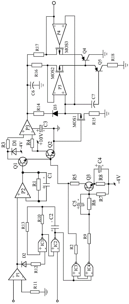
[0018] Such as figure 1 As shown, the present invention is made up of a power logic amplifier circuit, a switching power amplifier circuit connected to the power logic amplifier circuit, and a logic switch circuit connected in series between the power logic amplifier circuit and the switch power amplifier circuit. In order to achieve the present invention For the purpose, the present invention is also connected with a constant current circuit at the output end of the switching power amplifying circuit.

[0019] Wherein, the constant current circuit is the key point of the present invention, and it comprises operational amplifier P3, operational amplifier P4, field effect transistor MOS1, field effect transistor MOS2, field effect transistor MOS3, triode Q4, triode Q5.

[0020] In order to achieve the expected effect, the constant current circuit also includes a resistor R15 with one end connected to the drain of the field effect transistor MOS1 and the other end connected to t...


PUM


Abstract

The invention discloses a power amplifying logical circuit. The power amplifying logical circuit is characterized by mainly comprising a power logical amplify circuit, a switching power amplifying circuit and a logical switching circuit, wherein the switching power amplifying circuit is connected with the power logical amplifying circuit; the logical switching circuit is connected in series between the power logical amplifying circuit and the switching power amplifying circuit; the power logical amplifying circuit consists of a power amplifier P1, a NAND gate IC1, a NAND gate IC2, a diode D2 of which the pole N is connected with the output end of the power amplifier P1 and the pole P is connected with the cathode input end of the NAND gate IC1 after passing through a resistor R12, a resistor R13 of which one end is connected with the anode input end of the NAND gate IC1, and the like. The power amplifying logical circuit is simple in overall structure, and is convenient to manufacture and popularize. Meanwhile, the damping amplitude of an amplifying signal can be effectively lowered, so that the performance of the amplifying signal is ensured.

Description

technical field [0001] The invention relates to an amplifying circuit, in particular to a power amplifying logic system based on a constant current circuit. Background technique [0002] At present, the power amplifier circuit is widely used, and it mainly amplifies the power of the relevant voltage signal, current signal and other pulse signals according to the demand. However, the current of the conventional power amplifier circuit cannot maintain a constant value after the power drive amplification is performed, thus restricting its application range to a large extent. Contents of the invention [0003] The purpose of the present invention is to overcome the defect that the current of the traditional power amplifier circuit cannot be kept constant after power drive amplification, and to provide a power amplifier logic system based on a constant current circuit. [0004] The object of the present invention is achieved through the following technical solutions: a power a...

Claims


Application Information

Patent Timeline
Patent Type & Authority Applications(China)
IPC IPC(8): H03F3/217
CPCH03F1/26H03F3/211H03F3/2178H03F2200/114H03F2203/211
Inventor 周云扬
Owner CHENGDU CHUANGTU TECH
Why Eureka
Try Eureka