A thin film gas sensor
A gas sensor and thin film technology, which is applied in the field of gas detection, can solve the problems of poor selectivity and inability to distinguish several gas concentrations, and achieve the effect of overcoming poor selectivity
- Summary
- Abstract
- Description
- Claims
- Application Information
AI Technical Summary
Problems solved by technology
Method used
Image
Examples
Embodiment 1
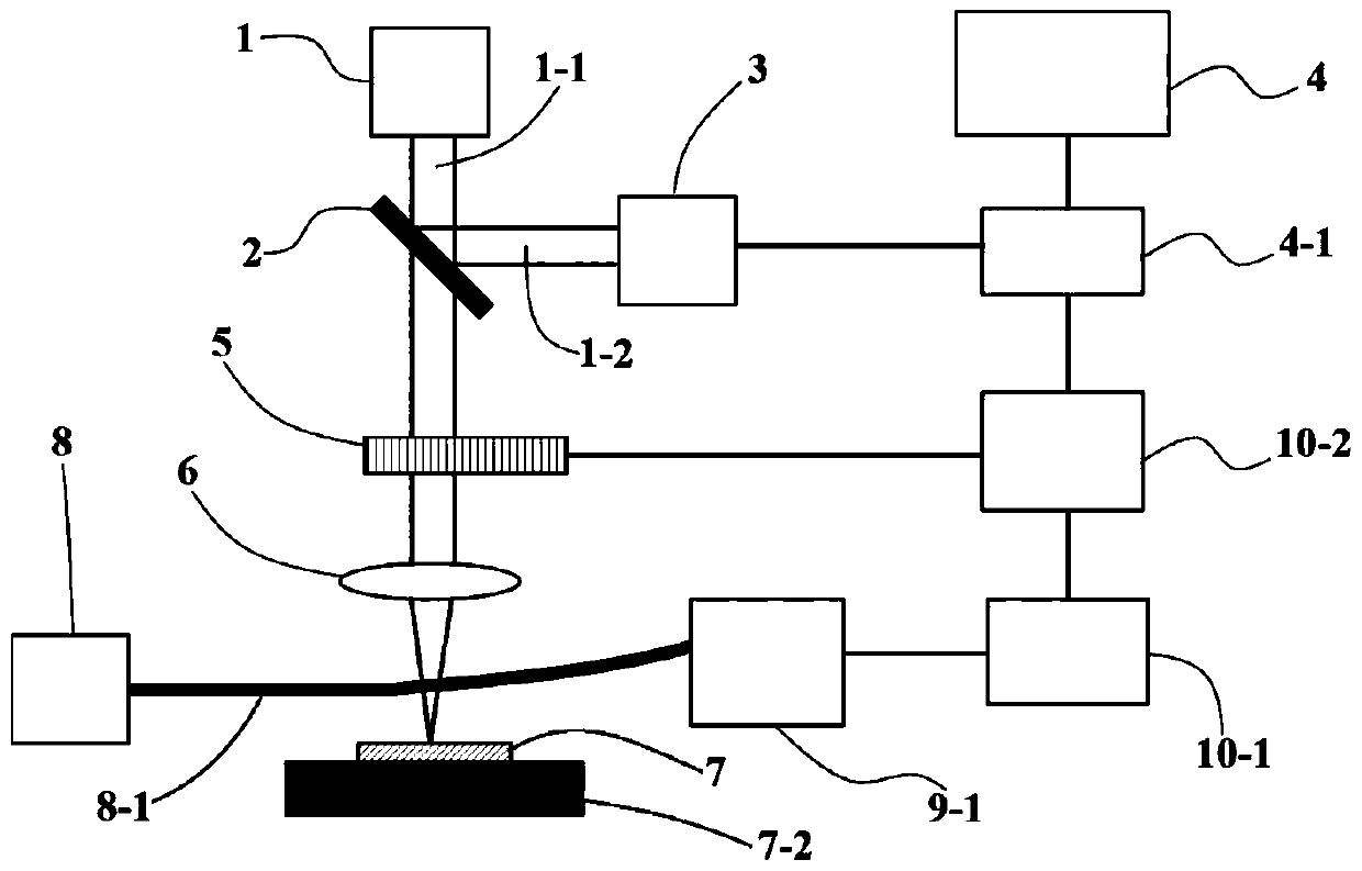
[0034] figure 1 Shown is the basic structure and working principle of this embodiment.
[0035] This embodiment adopts the principle of photothermal deflection. The pumping light source 1 emits pumping laser light, the pumping light 1-1 is first incident on the beam splitter 2, and a small part of the light is incident on the light intensity detector 3 as a normalized signal to eliminate the 1 measurement errors caused by power fluctuations; the light intensity detector 3 inputs the received signal into the A / D conversion module 4-1, and then into the host computer 4 for data collection; most of the light passes through the beam splitter 2, Then chopping by a chopper 5 performs amplitude modulation, and the effect of the chopper 5 is to give a periodic modulation signal to the pump light 1-1; the signal of the chopper 5 is connected to the lock-in amplifier 10-2 , to suppress optical noise; finally, the pump light 1-1 is focused by the focusing lens 6 onto the selective abso...
Embodiment 2
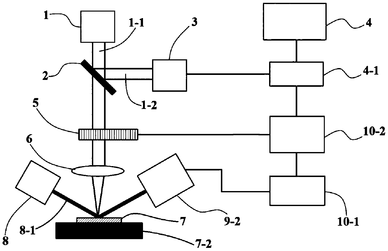
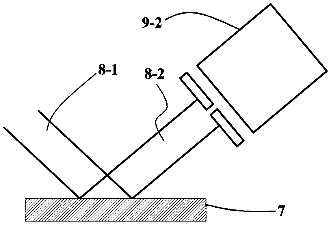
[0038] Such as figure 2 As shown, different from Embodiment 1, this embodiment adopts the principle of photothermal amplification. The detection light 8-1 is obliquely incident on the selective absorption film 7 at a certain angle; when the selective absorption film 7 has a strong reflection on the detection light, the pinhole light intensity detector 9-2 is placed on the detection light 8-1 on the reflected light path. Such as Figure 3a As shown, when the selective absorption film 7 does not absorb the gas, the reflected light 8-2 reflected by the selective absorption film 7 is not amplified; when the selective absorption film 7 absorbs the gas, and the wavelength of the pump light 1-1 is in the gas absorption peak, then the selective absorption film 7 will rise to a height due to heat absorption, forming a bulge 7-1 such as Figure 3b As shown, at this time, part of the detection light 8-1 will expand the beam due to the protrusion 7-1, forming a defocused reflected lig...
Embodiment 3
[0040]The difference between this embodiment and embodiment 2 is that when the selective absorption film 7 has strong transmission for the detection light, the pinhole light intensity detector 9-2 is placed on the transmission light path of the detection light 8-1. Such as Figure 4a As shown, when the selective absorption film 7 does not absorb gas, the transmitted light 8-5 transmitted by the detection light 8-1 through the selective absorption film 7 is not amplified; as Figure 4b As shown, when the selective absorption film 7 absorbs the gas, and the wavelength of the pump light 1-1 is at the absorption peak of the gas, then the selective absorption film 7 will bulge to form a bulge 7-1 due to heat absorption, and at this time part of the detection light 8-1 will cause beam expansion due to this protrusion 7-1, forming defocused transmitted light 8-6, so that the light intensity incident on the pinhole light intensity detector 9-2 will become weaker, and it can be inferre...
PUM
 Abstract
Description
Claims
Application Information
 - R&D
- Intellectual Property
- Life Sciences
- Materials
- Tech Scout
- Unparalleled Data Quality
- Higher Quality Content
- 60% Fewer Hallucinations
Browse by: Latest US Patents, China's latest patents, Technical Efficacy Thesaurus, Application Domain, Technology Topic, Popular Technical Reports.
© 2025 PatSnap. All rights reserved.Legal|Privacy policy|Modern Slavery Act Transparency Statement|Sitemap|About US| Contact US: help@patsnap.com


