
Radial drilling machine

A technology of radial drilling machine and cantilever, which is applied to the parts of boring machine/drilling machine, boring/drilling, drilling/drilling equipment, etc., to achieve the effects of improving stability, avoiding laborious adjustment, and simple structure

Inactive Publication Date: 2015-09-02
林飞飞
View PDF8 Cites 7 Cited by
  • Summary
  • Abstract
  • Description
  • Claims
  • Application Information

AI Technical Summary

Problems solved by technology

[0009] In order to make up for the deficiencies of the prior art, the present invention provides a radial drilling machine, which replaces the traditional way of using a lead screw for transmission, and directly sets an external thread on the column, avoiding the problems caused by the use of a lead screw. The invention adopts the telescopic cantilever, which solves the problems existing in the fixed cantilever

Method used


Image

  • Radial drilling machine
  • Radial drilling machine
  • Radial drilling machine

Examples


Embodiment Construction

[0030] In order to make the technical means, creative features, goals and effects achieved by the present invention easy to understand, the present invention will be further described below in conjunction with specific illustrations.

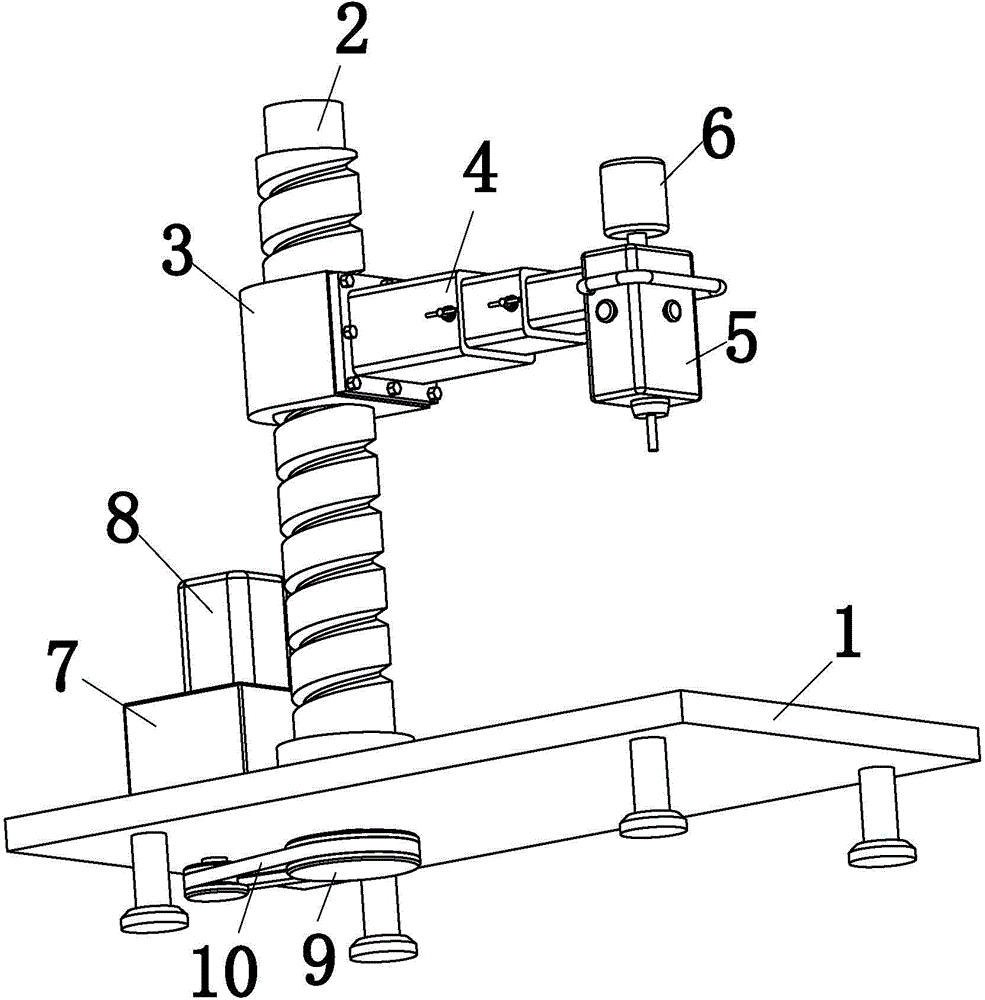
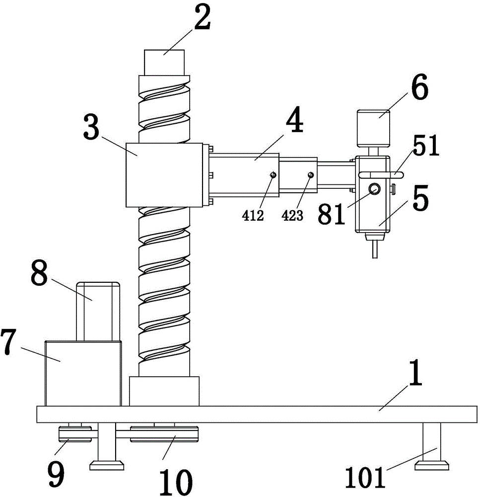
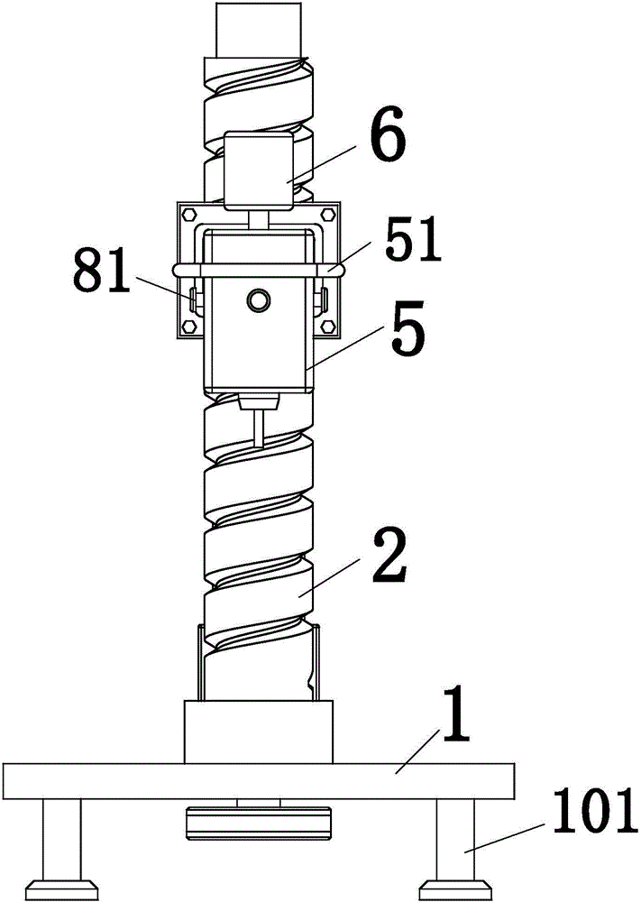
[0031] Such as Figure 1 to Figure 7 As shown, a radial drilling machine according to the present invention includes a base 1, a column 2, a moving slider 3, a telescopic cantilever 4, a gear box 5, a main motor 6, a lift adjustment reducer 7 and a lift adjustment motor 8. A leg 101 is provided below the base 1, the column 2 is located on the left side of the base 1, one end of the column 2 is connected to the base 1 through a bearing, the column 2 is provided with an external thread, and the column 2 is installed with the The mobile slider 3 matched with the external thread, the column 2 is used to support the telescopic cantilever 4 and drive the telescopic cantilever 4 to move up and down; one end of the telescopic cantilever 4 is fixed on th...


PUM


Abstract

The invention relates to the technical field of machining, in particular to a radial drilling machine. The radial drilling machine comprises a base, a stand column, a movable slider, a telescopic cantilever, a gear box, a main motor, a lifting adjustment speed reducer and a lifting adjustment motor. One end of the stand column is connected to the left side of the base through a bearing and is provided with an outer thread. The movable slider matched with the outer thread is mounted on the stand column. One end of the telescopic cantilever is fixed to the movable slider, and the other end of the telescopic cantilever is connected with the gear box. The main motor is connected with an input shaft of the gear box. The lifting adjustment speed reducer is positioned on the left side of the stand column, and an output shaft of the lifting adjustment speed reducer is in belt transmission with the stand column. The lifting adjustment motor is connected with an input shaft of the lifting adjustment speed reducer. The radial drilling machine has the advantages that conventional lead screw transmission modes are abandoned, the outer thread is arranged on the stand column directly, and accordingly, problems caused by use of lead screws are avoided; since the telescopic cantilever is adopted, problems of fixed cantilevers are solved.

Description

technical field [0001] The invention relates to the technical field of machining, in particular to a radial drilling machine. Background technique [0002] At present, the radial drilling machine is composed of a base, a column, a rocker arm, a gear box, a main motor, a lifting adjustment reducer, an auxiliary motor, and a lead screw. Among them, the lifting adjustment reducer is installed on the top of the column. The motor is installed on the casing of the lifting adjustment reducer, and the output shaft of the lifting adjustment reducer is connected with a fixed lead screw, and the lead screw is connected with the lead screw nut on the swing. The rocker arm needs to be rotated and adjusted frequently. Therefore, the lead screw and the lead screw nut on the rocker arm are likely to be not on the same axis. Once such a situation occurs, it will not only make the adjustment laborious, but also cause the lead screw to wear out. In severe cases, the serious consequences of bu...

Claims


Application Information

Patent Timeline
Patent Type & Authority Applications(China)
IPC IPC(8): B23B39/12B23B47/18B23B47/26B23Q1/44
CPCB23B39/12B23B47/26B23Q1/44B23Q5/22
Inventor 沈安邦
Owner 林飞飞
Learn More