Cover for battery case
A battery case and cover technology, applied in battery cover/end cover, secondary battery, battery pack components, etc., can solve problems such as cracking of safety valve 5, and achieve the effect of avoiding excessive stress concentration and reliable cracking
- Summary
- Abstract
- Description
- Claims
- Application Information
AI Technical Summary
Problems solved by technology
Method used
Image


Examples
Embodiment approach 1
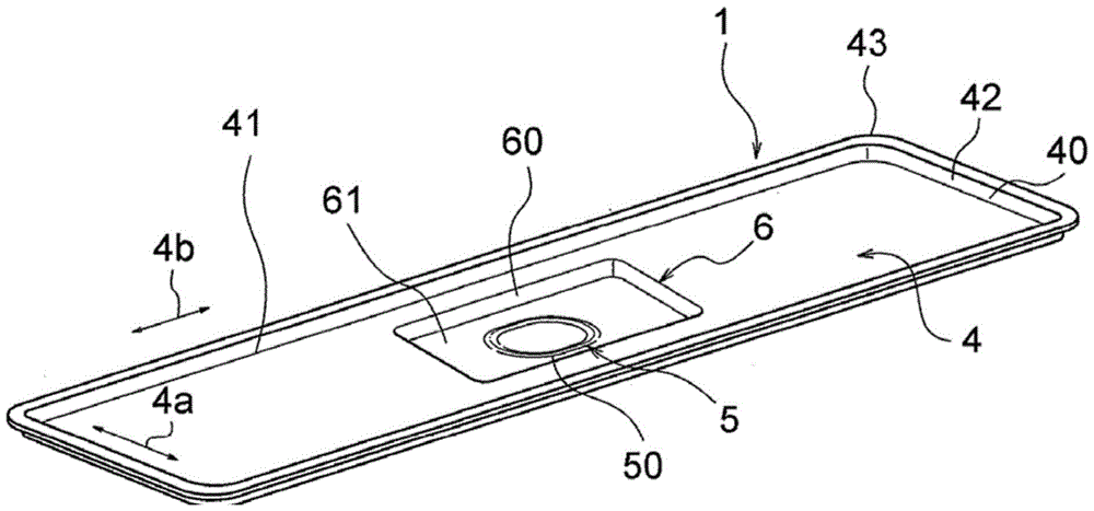
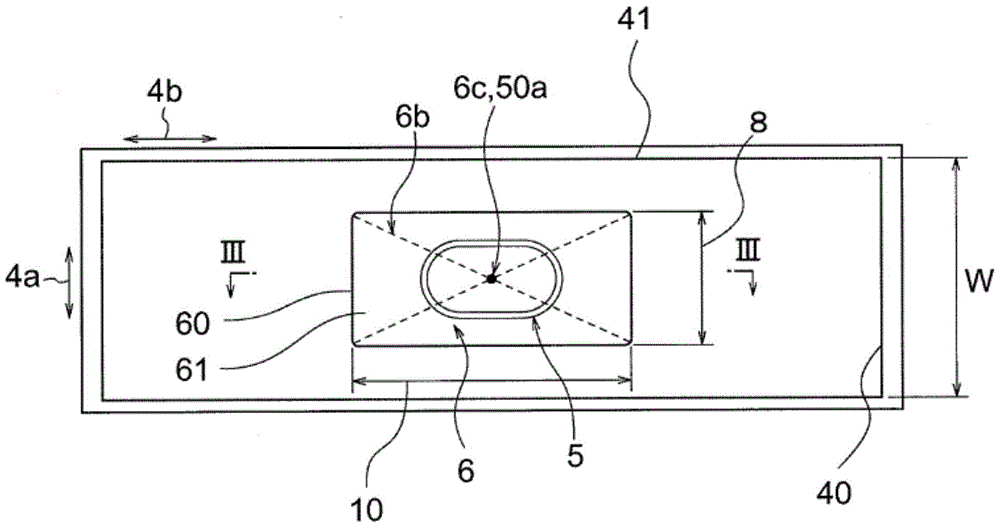
[0024] figure 1 It is a perspective view showing the lid body 1 for the battery case 3 according to Embodiment 1 of the present invention, figure 2 yes means figure 1 A top view of the cover body 1, image 3 is along figure 2 Cross-sectional view of line III-III. In addition, for the cover body used with the existing battery case (refer to Figure 6 as well as Figure 7 ) the same or equivalent parts are described using the same reference numerals. figure 1 The shown cover body 1 and the bottomed cylindrical shell main body 2 (refer to Figure 6 ) constitute together, for example, a battery case 3 (refer to Figure 6 ). The whole cover body 1 is comprised by the metal plate made from stainless steel.
[0025] The lid body 1 has a lid body body 4 , a safety valve 5 , and a protrusion 6 . Cover main body 4 such as figure 2 As shown, it is a substantially planar flat plate portion formed in a rectangular shape having a short side 40 and a long side 41 in plan view. ...
Embodiment approach 2
[0056] Figure 5 It is a plan view showing the lid body 1 for a battery case according to Embodiment 2 of the present invention. In Embodiment 1, although it was described that the center position 50a (center point) of the annular thin-walled portion 50 is arranged to coincide with the intersection point 6c of the two diagonal lines 6b connecting the opposite corners of the flat portion 61 (see figure 2 ), but in Embodiment 2, the intersection point 6c of the two diagonal lines 6b connecting the corners of the flat portion 61 of the annular thin-walled portion 50 is arranged inside the annular thin-walled portion 50 and connected to the annular thin-walled portion 50. The center position 50a of the portion 50 is not in the same position. Furthermore, the so-called inside of the annular thin portion 50 includes not only the inner side of the annular thin portion 50 but also the annular thin portion 50 itself. Other configurations are the same as those in Embodiment 1.
[00...
PUM
 Abstract
Description
Claims
Application Information
 - R&D
- Intellectual Property
- Life Sciences
- Materials
- Tech Scout
- Unparalleled Data Quality
- Higher Quality Content
- 60% Fewer Hallucinations
Browse by: Latest US Patents, China's latest patents, Technical Efficacy Thesaurus, Application Domain, Technology Topic, Popular Technical Reports.
© 2025 PatSnap. All rights reserved.Legal|Privacy policy|Modern Slavery Act Transparency Statement|Sitemap|About US| Contact US: help@patsnap.com