
Yaw Control System And Yaw Control Method For Wind Turbine Generator

A wind power generation device and yaw control technology, which is applied in the field of yaw control system, can solve problems such as cable damage or cutting, deterioration of the operating rate of wind power generation devices, and inability to detect the yaw direction value, etc., to achieve the effect of stable operation

Inactive Publication Date: 2015-08-26
MITSUBISHI HEAVY IND LTD
View PDF7 Cites 8 Cited by
  • Summary
  • Abstract
  • Description
  • Claims
  • Application Information

AI Technical Summary

Problems solved by technology

[0011] However, as described in Patent Document 2, in a wind turbine generator equipped with a potentiometer, when the potentiometer fails or malfunctions, an accurate yaw direction value may not be detected.
When the yaw maneuver of the nacelle continues in a state where the yaw direction value cannot be detected, various cables extending between the tower and the nacelle may be twisted beyond the limit
As a result, damage or cutting of these cables may occur, which may cause major unsuitability related to the safety of the wind power generation device.
[0012] On the other hand, when the operation of the wind power generator is stopped at the time when the potentiometer becomes abnormal, it is considered that, for example, in the case of the maintenance worker leaving the site in the middle of the night or the wind power generator on the ocean, it is not easy to access the wind power. In the case of power generation equipment, etc., when it is difficult to perform prompt maintenance work, the operation rate of wind power generation equipment will deteriorate significantly

Method used


Image

  • Yaw Control System And Yaw Control Method For Wind Turbine Generator
  • Yaw Control System And Yaw Control Method For Wind Turbine Generator
  • Yaw Control System And Yaw Control Method For Wind Turbine Generator

Examples


Embodiment Construction

[0091] Hereinafter, embodiments of the present invention will be described with reference to the drawings. However, dimensions, materials, shapes, relative arrangements, and the like of components described below or shown in the drawings as embodiments do not limit the scope of the present invention, but are merely illustrative examples.

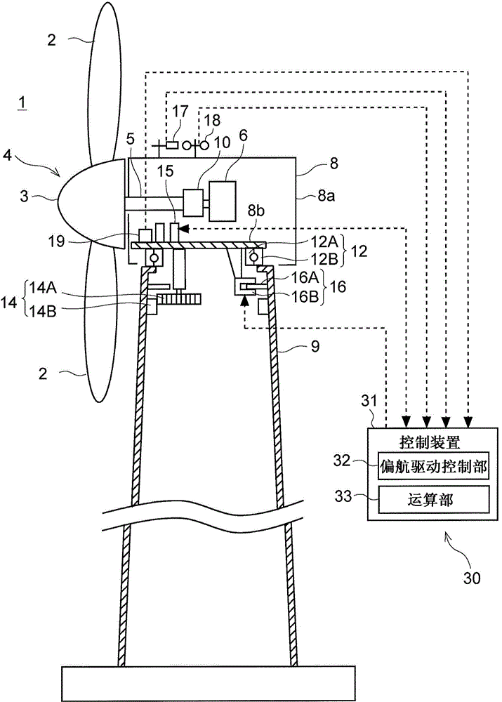
[0092] First, refer to figure 1 , a configuration example of the wind power generator 1 and the yaw control system 30 according to the embodiment of the present invention will be described. It should be noted, figure 1 It is a side view showing a schematic overall configuration of a wind power generator 1 according to one embodiment.

[0093] In several embodiments, figure 1 In the wind power generator 1 shown, a rotor 4 including at least two blades 2 and a hub 3 is rotated by wind energy. The hub 3 can be formed in one piece from a casting, with mountings for the blades 2 . For example, the wind power generator 1 may have a structure ...


PUM


Abstract

Provided are a yaw control system and a yaw control method for a wind turbine generator, which are capable of obtaining an accurate value of the yaw direction even when the yaw direction sensor is abnormal. A yaw control system for a wind turbine generator which includes a nacelle configured to be capable of yaw rotation by a yaw drive mechanism comprises: a yaw direction sensor for detecting a yaw direction value of the nacelle at a current time; a yaw rotation amount calculation part for calculating an amount of yaw rotation of the nacelle in a predetermined period of time based on a yaw rotation speed and a yaw rotation time of the nacelle; a yaw direction estimation part configured to calculate an estimate value of a yaw direction of the nacelle at an end point of the predetermined period by an estimate value calculation logic, based on the amount of yaw rotation in the predetermined period calculated by the yaw rotation amount calculation part and the yaw direction value at a starting point of the predetermined period, and a yaw drive control part for controlling the yaw drive mechanism, wherein the yaw drive control part is configured to: when the yaw direction sensor is normal, determine a yaw rotation direction of the nacelle based on a detected result of the yaw direction value detected by the yaw direction sensor; and when the yaw direction sensor is abnormal, determine the yaw rotation direction of the nacelle based on the estimate value calculated by the yaw direction estimation part.

Description

technical field [0001] The present disclosure relates to a yaw control system and a yaw control method of a wind power generator configured to receive wind power and generate electricity. Background technique [0002] In recent years, wind power generators utilizing wind power have attracted attention from the viewpoint of environmental protection. A wind power generator generally has a rotor in which a plurality of blades are attached to a hub. The rotor is mounted on a nacelle on a tower erected on land or in the sea. In such a wind power generator, the blades receive wind and the rotor rotates, and the rotation of the rotor is transmitted to a generator housed in the nacelle, and electric power is generated in the generator. [0003] In such a wind power generator, generally, the direction of the rotor is changed according to the direction of the wind in order to efficiently convert wind energy into rotational energy of the rotor. Therefore, there is known a wind power...

Claims


Application Information

Patent Timeline
Patent Type & Authority Applications(China)
IPC IPC(8): F03D7/04
CPCF03D7/0204Y02E10/72
Inventor 城井努马场满也
Owner MITSUBISHI HEAVY IND LTD
Learn More