Electric pusher for cutter grinder

A pusher and knife grinder technology, which is applied in the direction of grinding machine tool components, grinding/polishing equipment, other manufacturing equipment/tools, etc., can solve the problem of low work efficiency and achieve the effect of improving work efficiency and flexible grinding

Inactive Publication Date: 2015-08-26
谢博
View PDF7 Cites 2 Cited by
  • Summary
  • Abstract
  • Description
  • Claims
  • Application Information

AI Technical Summary

Problems solved by technology

However, the pusher of the currently commonly used sharpener is manually pushed, and the work efficiency is not high.

Method used


Image

  • Electric pusher for cutter grinder
  • Electric pusher for cutter grinder

Examples


Embodiment Construction

[0012] The preferred embodiments of the present invention will be described in detail below in conjunction with the accompanying drawings, so that the advantages and features of the present invention can be more easily understood by those skilled in the art, and the protection scope of the present invention will be defined more clearly.

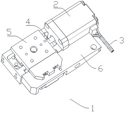
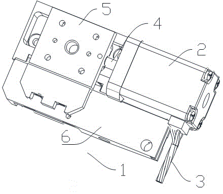
[0013] The invention provides an electric pusher for a sharpener with higher working efficiency.

[0014] Such as figure 1 , figure 2 As shown, an electric pusher 1 for a knife grinder includes a fixed base 6, on which a push slider 5 is provided, and the push slider 5 is controlled by a rotating shaft 4 to slide. The rotating shaft 4 is driven by a motor 2, and a motor control rod 3 is also provided on the motor 2.

[0015] Such as figure 1 , figure 2 As shown, the push slider 5 and the fixed base 6 are connected by sliding rails.

[0016] Such as figure 1 , figure 2 As shown, the motor 2 is an AC asynchronous motor.

[0017] The electric pushe...


PUM


Abstract

The invention discloses an electric pusher for a cutter grinder. The electric pusher comprises a fixing base, on which a pushing sliding block is arranged. The pushing sliding block is controlled by a rotary shaft to slide. The rotary shaft is driven by a motor, on which a motor control rod is arranged. The pushing sliding block and the fixing base are fixed by means of a sliding rail. The motor is an alternating-current asynchronous motor.The electric pusher for the cutter grinder has following beneficial effects: due to the fact that the fixing base is arranged on the electric pusher for the cutter grinder and provided with the pushing sliding block connected with the fixing base via the sliding rail, the pushing sliding block is controlled by the rotary shaft driven depending on the motor; the motor controls the rotary shaft to rotate in different directions such that the sliding block can be controlled to slide forwards and backwards, thereby achieving front-back pushing of items and flexible grinding; and working efficiency of the electric pusher for the cutter grinder is greatly increased.

Description

Technical field [0001] The invention relates to an electric pusher, more specifically, an electric pusher for a knife sharpener. Background technique [0002] Knife sharpener is a kind of industrial equipment that is commonly used in industrial production and has a relatively broad application prospect. However, the pusher of the currently commonly used sharpener is manual push, which is not efficient. Summary of the invention [0003] The invention mainly solves the technical problems existing in the prior art, so as to provide an electric pusher of the sharpener with higher working efficiency. [0004] The above technical problems of the present invention are mainly solved by the following technical solutions: [0005] An electric pusher for a knife sharpener includes a fixed base, on which a push slider is arranged, and the push slider is controlled by a rotating shaft to slide, and the rotating shaft is driven by a motor. A motor control lever is also provided on the motor desc...

Claims


Application Information

Patent Timeline
IPC IPC(8): B24B3/00B24B41/00
CPCB24B3/00
Inventor 谢博
Owner 谢博
Why Eureka
Try Eureka