Eureka AIR delivers breakthrough ideas for toughest innovation challenges, trusted by R&D personnel around the world.

Cavitation reactor

A generator and hydrodynamic cavitation technology, applied in chemical instruments and methods, chemical/physical processes, chemical/physical/physical chemical processes, etc., can solve the problem of poor cavitation effect and low cavitation efficiency of cavitation generators, etc. problem, to achieve the effect of reducing energy loss, good cavitation effect and high cavitation intensity

Inactive Publication Date: 2015-08-26
ICM INT CAVITENERGY MACHINES BEIJING
View PDF10 Cites 37 Cited by
  • Summary
  • Abstract
  • Description
  • Claims
  • Application Information

AI Technical Summary

Problems solved by technology

[0005] The technical problem to be solved by the present invention is: traditional cavitation generators have low cavitation efficiency and poor cavitation effect

Method used


Image

  • Cavitation reactor
  • Cavitation reactor
  • Cavitation reactor

Examples


Embodiment Construction

[0026] In the description of the present invention, it should be noted that unless otherwise specified and limited, the terms "installation", "connection" and "connection" should be understood in a broad sense, for example, it can be a fixed connection or a detachable connection. Connected, or integrally connected; it may be mechanically connected or electrically connected; it may be directly connected or indirectly connected through an intermediary, and it may be the internal communication of two components. Those of ordinary skill in the art can understand the specific meanings of the above terms in the present invention in specific situations. In addition, in the description of the present invention, unless otherwise specified, "plurality" means two or more

[0027] In order to make the purpose, technical solutions and advantages of the embodiments of the present invention clearer, the technical solutions in the embodiments of the present invention will be clearly and compl...


PUM


Abstract

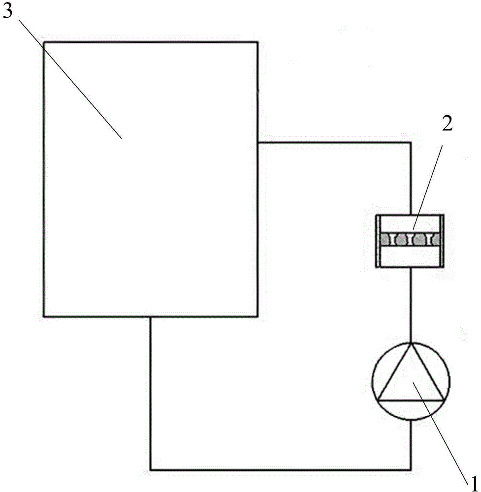
The invention relates to the technical field of hydrodynamic cavitation, in particular to a cavitation reactor. The cavitation reactor comprises a power device, a hydrodynamic cavitator and a water tank, wherein a plurality of Venturi type through holes are formed in each cavitation plate on the hydrodynamic cavitator, that is, hole reaming structures are arranged at two ends of each through hole, accordingly, the sectional area of each flow channel becomes small when water flows into the through holes in the cavitation plates from cavitation pipes, the water velocity is increased, and the water flow pressure is reduced; when the water flow pressure is decreased under the saturated vapor pressure of water, cavitation happens, cavitation bubbles are formed, then, the cavitation bubbles flow out of the cavitation plates with the water flow, the water pressure rises, the cavitation bubbles break, shock wave and microjet are formed at the moment the cavitation bubbles break, and high temperature and high pressure are generated. Compared with an existing straight-hole cavitation plate, the cavitation effect is better, and the cavitation efficiency is higher; a plurality of cavitation plates are connected together stage by stage and uniformly distributed in the cavitation pipes, the multi-stage cavitation reactor is formed, the energy utilization rate is greatly increased, and the cavitation effect is improved.

Description

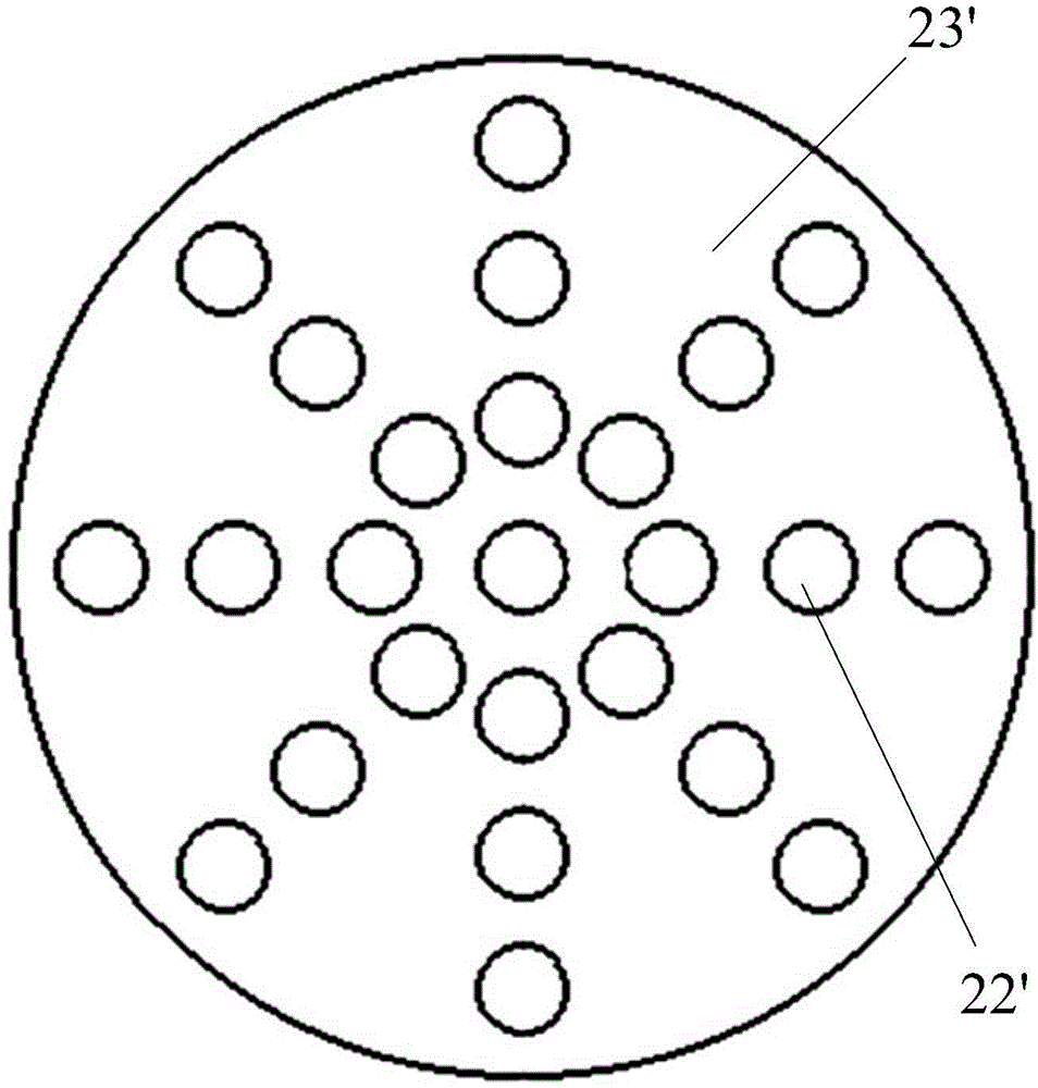
technical field [0001] The invention relates to the technical field of hydraulic cavitation, in particular to a cavitation generator. Background technique [0002] Currently, if figure 1 and figure 2 As shown, the cavitation efficiency of hydraulic cavitation technology is closely related to the cavitation device. Under certain external conditions, the cavitation device's structure, size, number of holes, and pore diameter are the main factors that determine the cavitation efficiency. In some cavitators, most of the through holes 22' on the cavitation plate 23' are straight holes, and the cavitation effect is poor. [0003] Therefore, in view of the above deficiencies, it is necessary to provide a cavitation generator with high cavitation efficiency and good cavitation effect. Contents of the invention [0004] (1) Technical problems to be solved [0005] The technical problem to be solved by the invention is: the traditional cavitation generator has low cavitation ef...

Claims


Application Information

Patent Timeline
Patent Type & Authority Applications(China)
IPC IPC(8): B01J19/00
Inventor 李九治
Owner ICM INT CAVITENERGY MACHINES BEIJING
Why Eureka
Eureka Blog
Learn More