
Systems and methods for controlling maximum power point tracking controllers

A technology of controllers and subsystems, applied in the direction of control/regulation systems, instruments, and adjustment of electrical variables, etc., can solve the problem of reverse current flowing through the second string, etc.

Active Publication Date: 2015-08-19
VOLTERRA SEMICONDUCTOR
View PDF7 Cites 3 Cited by
  • Summary
  • Abstract
  • Description
  • Claims
  • Application Information

AI Technical Summary

Problems solved by technology

This difference in illumination will cause the first string to generate a larger photocurrent than the second string, so that the two strings have different current-voltage characteristics, which may cause reverse current flow through the second string

Method used


Image

  • Systems and methods for controlling maximum power point tracking controllers
  • Systems and methods for controlling maximum power point tracking controllers
  • Systems and methods for controlling maximum power point tracking controllers

Examples


Embodiment Construction

[0042] As noted above, an MPPT controller can be used to operate a photovoltaic device at or near its MPP. However, conventional MPPT controllers often interfere with photovoltaic device production line testing. For example, conventional MPPT controllers may block reverse test current and / or overheat if performing EL testing. As another example, the transfer characteristics of a conventional MPPT controller will change during the transient high voltage test, thereby interfering with the determination of Voc, Isc and Pmp. Therefore, photovoltaic devices typically cannot be electrically coupled to conventional MPPT controllers during device production line testing.

[0043]This limitation of conventional MPPT controllers is a particularly serious disadvantage in applications where multiple MPPT controllers are packaged together with multiple photovoltaic devices. In these applications, MPPT controllers typically provide part of the interconnection between photovoltaic devices....


PUM


Abstract

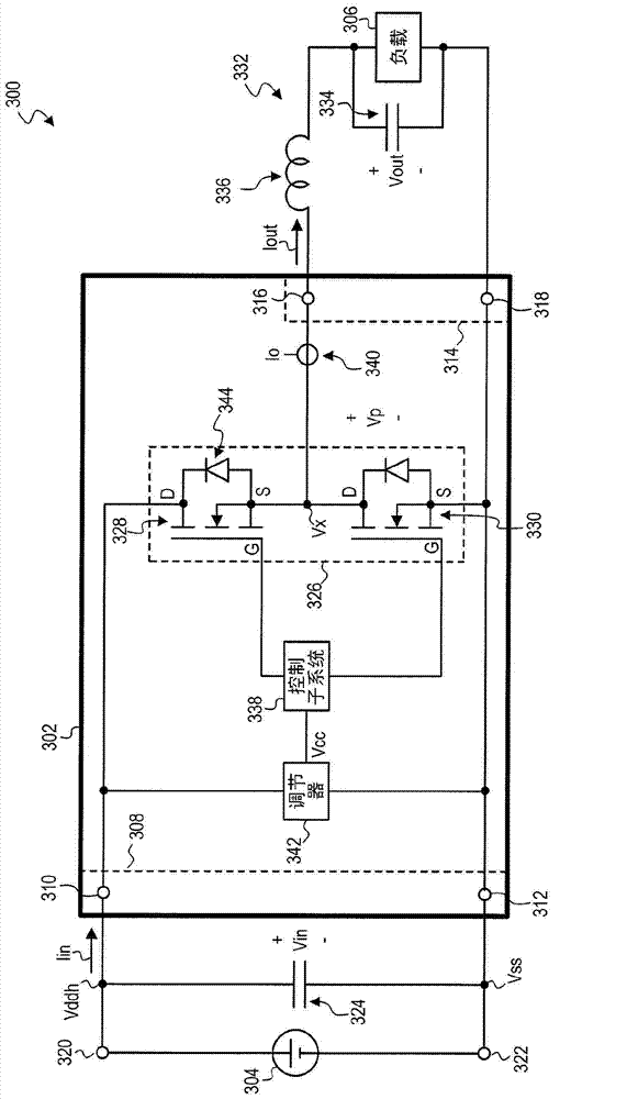
A method for operating a maximum power point tracking (MPPT) controller including a switching circuit adapted to transfer power between an input port and an output port includes the steps of: (a) in a first operating mode of the MPPT controller, causing a first switching device of the switching circuit to operate at a fixed duty cycle; and (b) in a second operating mode of the MPPT controller, causing a control switching device of the switching circuit to repeatedly switch between its conductive and non-conductive states to maximize an amount of power extracted from a photovoltaic device electrically coupled to the input port.

Description

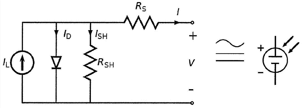
Background technique [0001] Photovoltaic cells produce a voltage that varies with current, cell operating conditions, cell physical properties, cell defects, and cell lighting. As shown in Figure 1, one mathematical model for photovoltaic cells models the output current as: [0002] I = I L - I 0 { exp [ q ( V + IR S ) n k T ] - 1 } - V + IR S R S H Equation 1 [0003] in [0004] ...

Claims


Application Information

Patent Timeline
IPC IPC(8): G05F1/67
CPCG05F1/67Y02E10/58Y02E10/56
Inventor A·J·斯特拉塔克斯M·D·麦克吉姆赛I·耶尔格维奇K·姚X·张V·W·吴
Owner VOLTERRA SEMICONDUCTOR
Learn More