
Roof bars for a motor vehicle

A technology for motor vehicles and vehicle roofs, applied in vehicle parts, additional accessories, transportation and packaging, etc., can solve the problem of not providing tolerance compensation, and achieve the effect of reliable and durable clamping, easy one-hand manipulation, and reliable locking

Inactive Publication Date: 2015-08-19
AUDI AG
View PDF6 Cites 11 Cited by
  • Summary
  • Abstract
  • Description
  • Claims
  • Application Information

AI Technical Summary

Problems solved by technology

The disadvantage of known tensioning mechanisms via levers or eccentrics is that they do not provide tolerance compensation in rigid levers and require additional structural components for creating the clamping stress

Method used


Image

  • Roof bars for a motor vehicle
  • Roof bars for a motor vehicle
  • Roof bars for a motor vehicle

Examples


Embodiment Construction

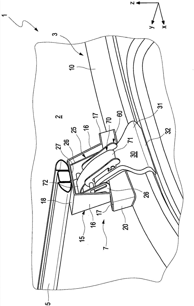
[0024] figure 1 A roof base cross member 1 for a motor vehicle is shown in a locked state, which is mounted on a vehicle roof 2 and is known for receiving loads or luggage, such as skis or the like. For this purpose, usually two roof base cross members 1 are fastened to the vehicle roof 2 , one facing the front of the vehicle and one facing the rear of the vehicle.

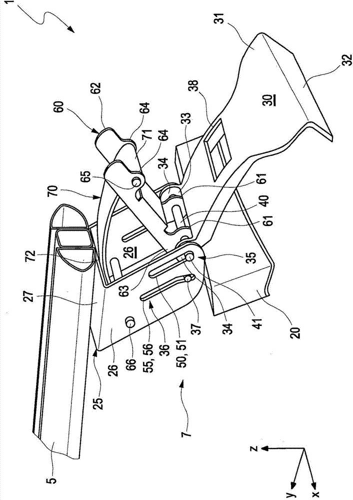
[0025] Each roof base cross member 1 has a Figures 1 to 4 The top beam element 5 which is only partially shown in the figure is designed as a hollow profile in the illustrated embodiment. The roof member 5 is attached to the side wall longitudinal members 10 or to the side wall frame of the body 3 via two opposing support structures 7 on the roof 2 . To this end, the supporting structures 7 each have a first outer U-shaped profile element 15 with two legs 16 each with a foot 17 and a connecting element 18 . The U-shape of the first profiled element 15 is formed by two legs 16 and a first connecting element 18 ...


PUM


Abstract

Roof bars (1) for a motor vehicle, having a support structure (7) for a roof bar element (5) with an attachment claw (30) which engages at a first end (31) on a side wall rail (10) of a vehicle body (3) and is connected in an articulated fashion to a clamping lever (60). According to the invention, the attachment claw (30) is guided in a guide (50) in the support structure (7) and a leaf spring (70) is provided which, on the one hand, engages on the clamping lever (60) in the region of its free end (62) and, on the other hand, is supported on the support structure (7), wherein when the clamping lever (60) is pressed down towards the attachment claw (30) by the spring force the attachment claw (30) is clamped on the side wall rail (10).

Description

technical field [0001] The invention relates to a roof base cross member for a motor vehicle according to the preamble of claim 1 . Background technique [0002] A number of variants of such roof base members for motor vehicles are known. They are used to transport loads on the roof and are designed as so-called clamping brackets. Usually two clamping brackets are arranged on the vehicle roof, one towards the front of the vehicle and one towards the rear of the vehicle, said clamping brackets are also referred to as ejector bars. The roof base cross member is secured by special clamping feet or clamping claws which can be clamped to the side wall frame of the motor vehicle. Various structures are used here as tensioning means. A disadvantage of the known tensioning mechanisms by means of levers or eccentrics is that they do not provide tolerance compensation in rigid levers and require additional structural components for creating the clamping stress. [0003] A clampabl...

Claims


Application Information

Patent Timeline
Patent Type & Authority Applications(China)
IPC IPC(8): B60R9/058
CPCB60R9/058
Inventor S·施尔克M·沙费尔C·伯格S·斯特雷贝尔
Owner AUDI AG
Learn More