Linear motion device with elastic housing

A technology of linear motion and shell, applied in the direction of linear motion bearings, electromechanical devices, electric components, etc., can solve the problems of unusable guide rails, etc., and achieve the effect of saving materials and improving rigidity

Active Publication Date: 2015-08-19
ROBERT BOSCH GMBH
View PDF7 Cites 1 Cited by
  • Summary
  • Abstract
  • Description
  • Claims
  • Application Information

AI Technical Summary

Problems solved by technology

[0007] However, with this solution comes the following situation: the conventional mounting method explained above can no longer be used for the guide rail, because the frictional force between the second guide rail and the second housing side wall So large that when the tabletop part is moved along the housing, the orientation of the second guide rail no longer occurs, but only more bending of the second housing side wall occurs

Method used


Image

  • Linear motion device with elastic housing
  • Linear motion device with elastic housing
  • Linear motion device with elastic housing

Examples


Embodiment Construction

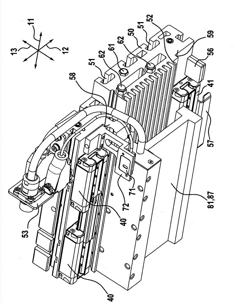
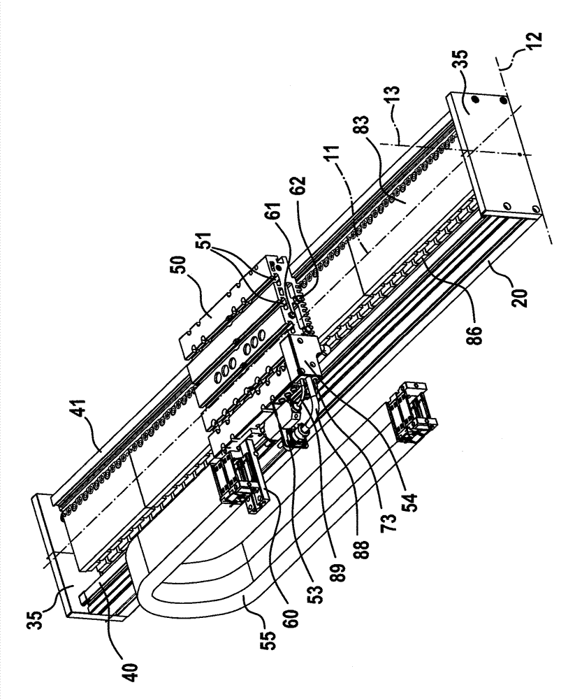
[0090] figure 1 A perspective view of the linear motion device 10 according to the invention is shown. The linear motion device 10 comprises a housing 20 which extends along the longitudinal axis 11 with a constant, U-shaped cross-sectional shape. The housing 20 is made of aluminum and is produced by extrusion. However, it is also conceivable to produce the housing 20 chip-free, in particular by milling. On the two longitudinal ends of the housing 20 , a rectangular end plate is respectively arranged, and the end plates are screwed together with the housing 20 . Furthermore, straight first and second guide rails 40 , 41 are fastened to the housing 20 , said first and second guide rails being parallel to the longitudinal axis over almost the entire length of the housing 20 11 extensions. Two first or two second guide vehicles respectively (in image 3 reference numerals 40 , 41 ) are supported on the first and second guide rails 40 , 41 in a movable manner in the direction...


PUM


Abstract

The invention relates to a linear motion device (10) comprising a housing (20) extending along the longitudinal axis (11), the housing has a U-Shaped cross-sectional shape, the U-Shaped cross-sectional shape has a housing base (21) and a first housing side wall and a second housing side wall (22, 23). According to the invention, the bending elasticity of the second housing side wall (23) is greater than that of the first housing side wall (22), the housing side wall (23) bends at a degree of 80%, preferably, 90% to bear the length change of a desk member along a transverse axis caused by the heating.

Description

technical field [0001] The invention relates to a linear motion device according to the preamble of claim 1 and to a method for mounting the linear motion device. Background technique [0002] A linear movement device is known from DE 10 2011 111 849 A1. The linear motion device includes a housing extending in the direction of the longitudinal axis, wherein the housing has a U-shaped cross-sectional shape, and the U-shaped cross-sectional shape has a housing base and a first The housing side wall and a second housing side wall. The housing base defines a transverse axis oriented perpendicular to the longitudinal axis, wherein a vertical axis is perpendicular to the longitudinal axis and oriented perpendicular to the transverse axis. A first guide rail, which extends in the direction of the longitudinal axis, is attached to the end of the first housing side wall facing away from the housing base. Two first guided vehicles are supported in a linearly movable manner on the f...

Claims


Application Information

Patent Timeline
Patent Type & Authority Applications(China)
IPC IPC(8): H02K41/02
CPCH02K41/031F16C29/004F16C29/008F16C29/123H02K5/06H02K11/21
Inventor J.迪尔施巴赫尔M.施托克F.瓦尔姆特B.克尼格
Owner ROBERT BOSCH GMBH
Why Eureka
Try Eureka