
Pneumatic tire

A technology of pneumatic tires and tires, which is applied to tire parts, tire tread/tread pattern, transportation and packaging, etc., to achieve good control stability and small deformation

Active Publication Date: 2015-08-19
SUMITOMO RUBBER IND LTD
View PDF7 Cites 7 Cited by
  • Summary
  • Abstract
  • Description
  • Claims
  • Application Information

AI Technical Summary

Problems solved by technology

[0004] However, in Patent Documents 1 and 2, the relationship between the number of shoulder lateral grooves on the inner tread end side and the number of shoulder lateral grooves on the outer tread end side is still not considered, so the handling stability There is room for further improvement

Method used


Image

  • Pneumatic tire
  • Pneumatic tire
  • Pneumatic tire

Examples


Embodiment 1

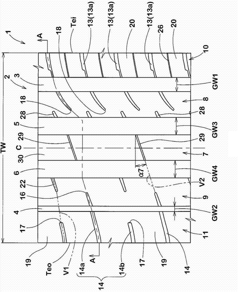
[0079] The tire of Example 1 has the above figure 1 tread pattern. Example 2 has Figure 6 Tread pattern shown. In Example 2, such as Figure 6 As shown, compared with Embodiment 1, the central lateral grooves are arranged half pitch staggered along the tire circumferential direction. The tire of the comparative example is a tire in which the second outer shoulder lateral groove of Example 1 extends toward the inner side in the tire axial direction beyond the outer shoulder main groove. Thus, the number of first inner shoulder lateral grooves is set to be equal to the number of first outer shoulder lateral grooves. The test method is as follows.

[0080]

[0081] A professional driver drives a test vehicle equipped with test tires on a test track, and evaluates the steering stability of each tire sensory, including steering wheel responsiveness, rigidity, and grip. The results are represented by the comparative example with a rating of 100, and the larger the numerical...


PUM


Abstract

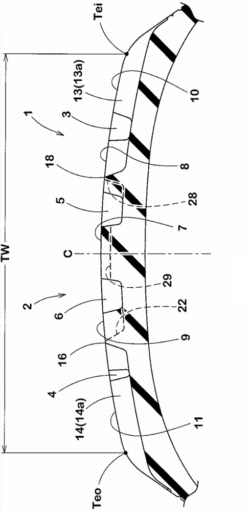
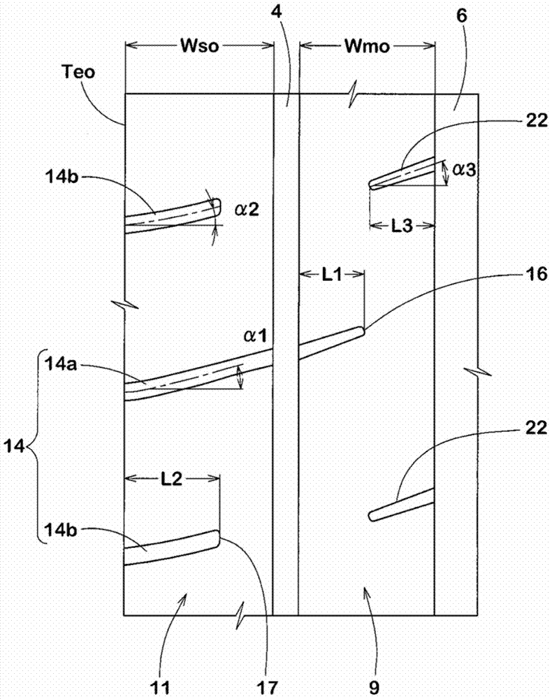
A pneumatic tire includes a tread portion provided with circumferentially extending main grooves and lateral grooves. The main grooves include an inboard shoulder main groove, an outboard shoulder main groove, an inboard center main groove and an outboard center main groove. The lateral grooves includes a plurality of first outboard shoulder lateral grooves each having an axially inner end positioned between the outboard shoulder main groove and the outboard center main groove, and a plurality of first inboard shoulder lateral grooves each having an axially inner end positioned between the inboard shoulder main groove and the inboard center main groove, wherein the number of the first inboard shoulder lateral grooves is greater than the number of the first outboard shoulder lateral grooves.

Description

technical field [0001] The present invention relates to a pneumatic tire having good handling stability. Background technique [0002] Patent Documents 1 to 2 below propose a pneumatic tire in which the orientation when mounted on a four-wheeled automobile (hereinafter, may be simply referred to as a "vehicle") is specified. [0003] Patent Documents 1 and 2 propose a pneumatic tire in which the groove widths of a plurality of longitudinal grooves provided in a tread portion are correlated with each other. [0004] However, in Patent Documents 1 and 2, the relationship between the number of shoulder lateral grooves on the inner tread end side and the number of shoulder lateral grooves on the outer tread end side is still not considered, so the control stability There is still room for further improvement. [0005] Patent Document 1: Japanese Patent Laid-Open No. 2012-218650 [0006] Patent Document 2: Japanese Patent Laid-Open No. 2013-151236 Contents of the invention ...

Claims


Application Information

Patent Timeline
Patent Type & Authority Applications(China)
IPC IPC(8): B60C11/03
CPCB60C11/12B60C11/03B60C11/04B60C11/0304B60C2011/0381B60C2011/0353B60C11/0306B60C2011/0388B60C2011/0341B60C2011/0372B60C11/042B60C2011/0358
Inventor 永原直哉
Owner SUMITOMO RUBBER IND LTD
Learn More