Material clamp

A fixture and material body technology, which is applied in the field of material taking devices, can solve the problems of high risk factor, low efficiency of manual material taking, and mold crushing.

Active Publication Date: 2015-08-19
GREE ELECTRIC APPLIANCES INC
View PDF13 Cites 5 Cited by
  • Summary
  • Abstract
  • Description
  • Claims
  • Application Information

AI Technical Summary

Problems solved by technology

[0002] At present, the nozzle material of injection molded parts generally adopts the method of manual retrieving. Because the temperature of the injection molded part is very high when it is just taken out, the efficiency of manual retrieving is low, and the risk factor is relatively high.
However, if the robot is used for automatic production, because it is impossible to know whether the material is clamped or not, if the material is not clamped, if the follow-up operation is performed, the mold will be crushed because the material is not taken out.

Method used


Image

  • Material clamp
  • Material clamp
  • Material clamp

Examples


Embodiment Construction

[0020] Hereinafter, the present invention will be described in detail with reference to the drawings and examples. It should be noted that, in the case of no conflict, the embodiments in the present application and the features in the embodiments can be combined with each other.

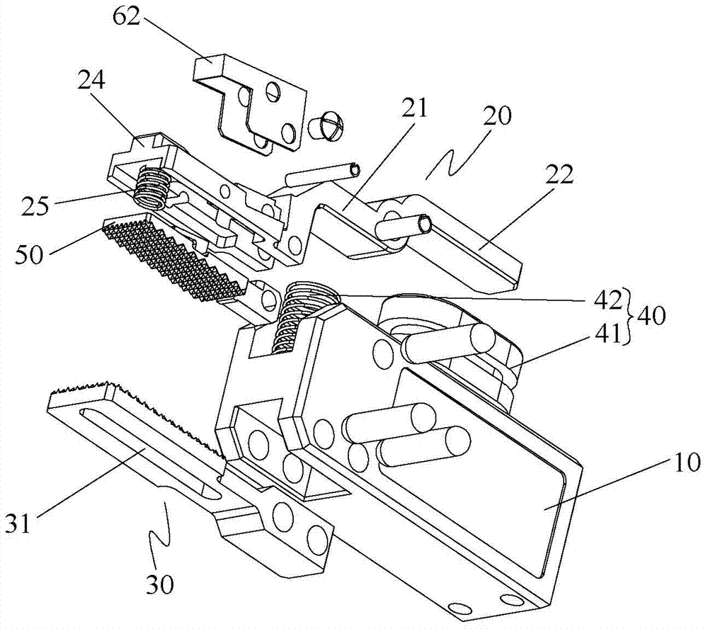
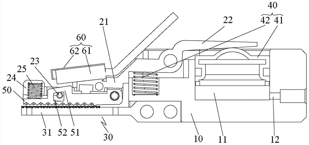
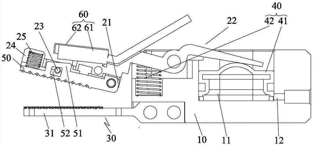
[0021] Such as Figure 1 to Figure 3 As shown, according to the embodiment of the present invention, the material clamp includes a mounting seat 10 , a first clamping part 20 , a second clamping part 30 , a driving mechanism 40 , a movable clamping part 50 and a detection mechanism 60 . The first clamping portion 20 is pivotally connected to the mounting base 10 and includes a first clamping end 21 and a driving end 22 . The second clamping portion 30 is fixedly connected to the mounting base 10 and includes a second clamping end 31 . The driving mechanism 40 is disposed on the mounting base 10 and drives the first clamping end 21 to approach or move away from the second clamping end 31 . The mova...


PUM


Abstract

The invention provides a material clamp. The material clamp comprises a mounting seat (10), a first clamping portion (20), a second clamping portion (30), a driving mechanism (40), a movable clamping part (50) and a detection mechanism (60). The first clamping portion (20) is pivoted on the mounting seat (10) and comprises a first clamping end (21) and a driving end (22); the second clamping portion (30) comprises a second clamping end (31), and the driving mechanism (40) is arranged on the mounting seat (10) and drives the first clamping end (21) to be close to or far away from the second clamping part (31); a limiting part (23) for limiting the rotation position of the movable clamping part (50) is arranged on the first clamping portion (20), and clamping space is formed between the movable clamping part (50) and the second clamping end (31); and the detection mechanism (60) detects the clamping position of the movable clamping part (50) and determines whether a material is clamped by the material clamp or not according to a detection result. According to the material clamp, material clamping and taking out can be effectively determined, and the mold production safety is improved.

Description

technical field [0001] The invention relates to the field of material taking devices, in particular to a material body clamp. Background technique [0002] At present, the nozzle material of injection molded parts generally adopts the method of manual retrieving, because the temperature of the injection molded part is very high when it is just taken out, so the efficiency of manual retrieving is low, and the risk factor is relatively high. However, if the automatic production of the manipulator is used, since it is impossible to know whether the material is clamped or not, if the material is not clamped, if the follow-up operation is performed, the mold will be crushed because the material is not taken out. Contents of the invention [0003] The present invention aims to provide a material body clamp, which can effectively determine the clamping and removal of the material body and improve the safety of mold production. [0004] In order to achieve the above object, accor...

Claims


Application Information

Patent Timeline
Patent Type & Authority Applications(China)
IPC IPC(8): B29C45/17B29C45/76
CPCB29C45/40B29C45/76B29C2045/7633
Inventor 李廷喜
Owner GREE ELECTRIC APPLIANCES INC
Why Eureka
Try Eureka