Method and system for evaluating redox flow battery
A liquid flow battery and oxidation value technology, applied in fuel cells, fuel cell additives, regenerative fuel cells, etc., can solve problems such as redox flow battery capacity attenuation
- Summary
- Abstract
- Description
- Claims
- Application Information
AI Technical Summary
Problems solved by technology
Method used
Image
Examples
no. 1 example
[0035] First embodiment - mode for assessing state of charge
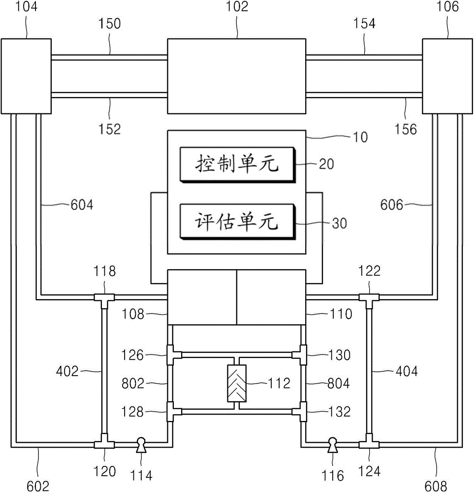
[0036] Figure 4 is a schematic diagram showing the operation of the redox flow battery evaluation system according to the first embodiment of the present disclosure.
[0037] refer to Figure 4 , the control unit 20 controls the opening / closing states of the three-way valves 118, 120, 122, 124, 126, 128, 130, and 132, thereby controlling the path of the flow channel, so that the electrolyte discharged from the electrolyte tanks 104 and 106 is reintroduced into the electrolyte tank after passing through the detection cells 108 and 110 104 and 106. The opening / closing states of the three-way valve controlled by the control unit 20 in the first embodiment are as follows:
[0038] - Three-way valves 118, 120, 122, 124, 126, 128, 130 and 132: "closed" state.
[0039] Specifically, the three-way valves 118, 120, 122, 124, 126, 128, 130, and 132 are all maintained in the "closed" state, and the moving paths of the ...
no. 2 example
[0077] Second embodiment - mode for assessing capacity fade
[0078] Figure 6 is a schematic diagram showing the operation of the redox flow battery evaluation system according to the second embodiment of the present disclosure.
[0079] refer to Figure 6, the control unit 20 is configured to control the opening / closing states of the three-way valves 118, 120, 122, 124, 126, 128, 130, and 132, thereby controlling the path of each flow channel, so that the electrolyte discharged from the detection cells 108 and 110 does not pass through the tanks 104 and 106 or The stirrer 112 is reintroduced into the detection cells 108 and 110 . The opening / closing state of the three-way valve controlled by the control unit 20 in the second embodiment is as follows:
[0080] - three-way valves 126, 128, 130 and 132: "closed" state;
[0081] - Three-way valves 118, 120, 122 and 124: "open" state.
[0082] Therefore, the movement paths of the first electrolyte and the second electrolyt...
no. 3 example
[0095] Third Example - Mode for Estimating Oxidation Value
[0096] Figure 8 is a schematic diagram showing the operation of the redox flow battery evaluation system according to the third embodiment of the present disclosure.
[0097] refer to Figure 8 , the control unit 20 is configured to control the opening / closing states of the three-way valves 118, 120, 122, 124, 126, 128, 130, and 132, thereby controlling the path of each flow channel, so that the electrolyte discharged from the detection cells 108 and 110 is reintroduced after passing through the stirrer 112 to the detection batteries 108 and 110. The opening / closing state of the three-way valve controlled by the control unit 20 in the third embodiment is as follows:
[0098] - Three-way valves 118, 120, 122, 124, 126, 128, 130 and 132: "open" state.
[0099] Specifically, the three-way valves 118, 120, 122, 124, 126, 128, 130, and 132 are all maintained in the "open" state, and the movement paths of the first ...
PUM
 Abstract
Description
Claims
Application Information
 - R&D
- Intellectual Property
- Life Sciences
- Materials
- Tech Scout
- Unparalleled Data Quality
- Higher Quality Content
- 60% Fewer Hallucinations
Browse by: Latest US Patents, China's latest patents, Technical Efficacy Thesaurus, Application Domain, Technology Topic, Popular Technical Reports.
© 2025 PatSnap. All rights reserved.Legal|Privacy policy|Modern Slavery Act Transparency Statement|Sitemap|About US| Contact US: help@patsnap.com


