
Alcohol group liquid fuel vaporizing combustor

A liquid fuel and burner technology, applied in the direction of burner, combustion method, combustion type, etc., can solve problems such as blockage of gasification pipe and burner nozzle, failure to use normally, unstable firepower, etc., and achieve gas pressure balance and convenience The effect of promoting the use and avoiding potential safety hazards

Active Publication Date: 2015-08-12
广东你好智能科技有限公司
View PDF13 Cites 15 Cited by
  • Summary
  • Abstract
  • Description
  • Claims
  • Application Information

AI Technical Summary

Problems solved by technology

However, the alcohol-based liquid fuel based on methanol also has its own disadvantages: the calorific value of alcohol-based liquid fuel is low, and it is not suitable for ordinary stoves. The traditional atomization combustion method cannot make it fully burnt, and the energy consumption is high; if When the heating gasification combustion method is adopted, when the temperature reaches about 250 degrees, it is easy to form carbon deposits, block the gasification tube and the nozzle of the burner head, and cause the firepower to be unstable or even cannot be used normally; if there is no good burner to match it, Alcohol-based liquid fuels cannot be popularized
[0007] Its combustion structure is relatively complex, and there are unstable factors in the gasification effect, so the heating effect is not ideal

Method used


Image

  • Alcohol group liquid fuel vaporizing combustor
  • Alcohol group liquid fuel vaporizing combustor
  • Alcohol group liquid fuel vaporizing combustor

Examples


Embodiment Construction

[0043] In order to enable those skilled in the art to better understand the technical solution of the present invention, the present invention will be described in detail below in conjunction with the accompanying drawings. The description in this part is only exemplary and explanatory, and should not have any limiting effect on the protection scope of the present invention. .

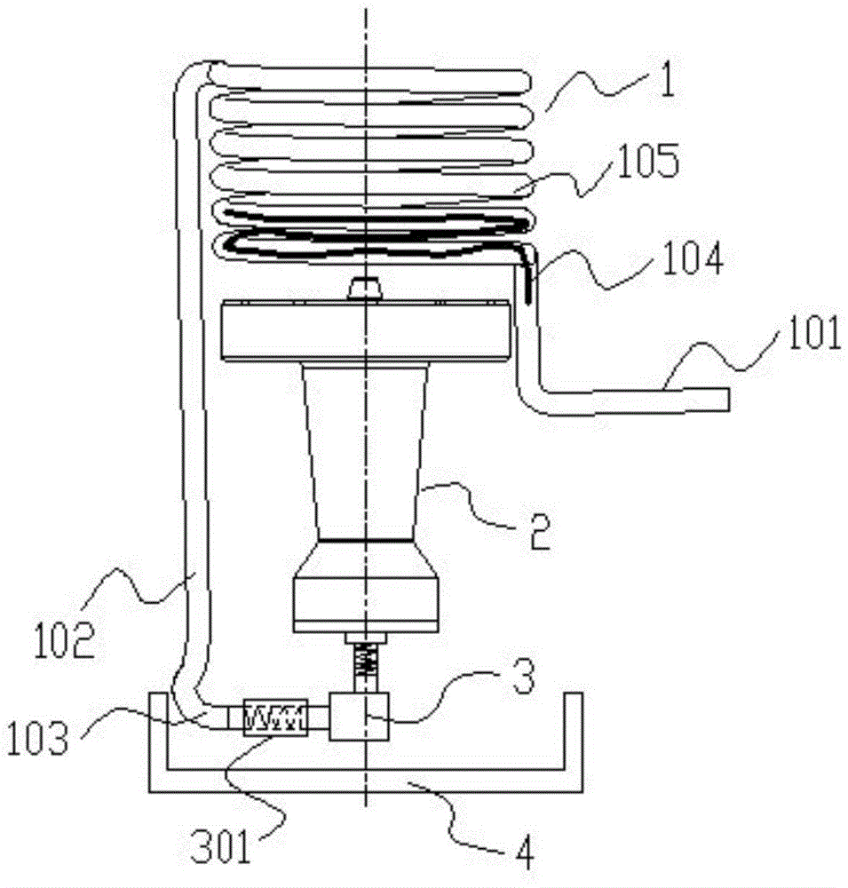
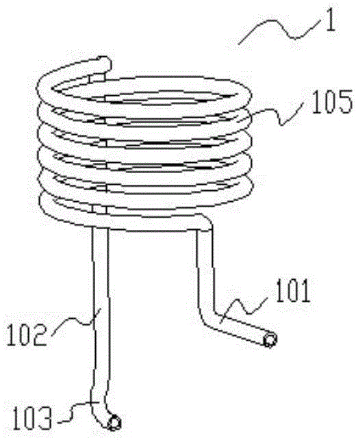
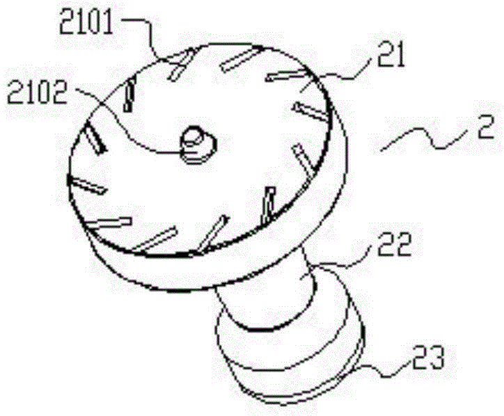
[0044] Such as Figure 1-Figure 9 As shown, the specific structure of the present invention is: it includes a fire distributor 2 and a gasification pipe 1 connected thereto, the fire distributor 2 is placed in the combustion cylinder 7, and the gasification pipe 1 is a multi-turn spiral formed by a metal pipe. Close-packed columnar structure, which is arranged directly above the fire distributor 2; the feed pipe 101 of the gasification pipe 1 is at the bottom of the spiral and spirals upward from the position of the fire distributor 2; the delivery pipe 1 of the gasification pipe 1 Trachea 102 falls v...


PUM


Abstract

The invention discloses an alcohol group liquid fuel vaporizing combustor, and belongs to the field of heating equipment. The alcohol group liquid fuel vaporizing combustor comprises a fire distributor and a vaporizing pipe connected with the fire distributor, wherein the fire distributor is arranged in a combustion barrel, the vaporizing pipe is of a multi-coil densely arranged columnar structure formed by a metal pipe spirally and is arranged over the fire distributor, and a feeding pipe of the vaporizing pipe is located at the lowest position of the spiral and spirals upwards from the position of the fire distributor; a gas transmitting pipe of the vaporizing pipe vertically falls down from the highest position and is connected with the bottom of the fire distributor through a spraying nozzle connector; an ignition basin is arranged under the fire distributor; the fire distributor is composed of a fire distribution cover on the upper portion, a mixer in the middle and a base cover on the lower portion, the center of the fire distribution cover is sealed, and a plurality of gas spraying holes are formed in the periphery of the surface of the fire distribution cover. The alcohol group liquid fuel vaporizing combustor is automatically heated in the combustion process without a power source or other heat resources, the vaporizing process is uniform, combustion is stable, fire is large, the heating effect is good, no fuel flies out, blockage of the vaporizing pipe is avoided, and the alcohol group liquid fuel vaporizing combustor is convenient to use and popularize.

Description

technical field [0001] The invention belongs to the field of heating equipment, in particular to an alcohol-based liquid fuel gasification burner. Background technique [0002] The burner is an essential heating tool for households, catering, hot pot restaurants and field operations. At present, due to the shortage of oil resources, the liquefied gas refined from oil is in short supply. In addition, the investment in laying natural gas pipelines is huge and the cycle is long. Therefore, the market supply Insufficient, severe shortage; Diesel and kerosene are prohibited from being used in catering, industry and other industries due to their high prices, no promotional value, and serious pollution. In order not to be affected by oil resources, various countries have increased their efforts to develop other alternative energy sources. As a kind of renewable energy, methanol and ethanol have been paid attention to by various countries, and they have all increased the developmen...

Claims


Application Information

Patent Timeline
IPC IPC(8): F23D11/00F23D11/36F23D11/44
CPCF23D11/00F23D11/36F23D11/44
Inventor 唐波
Owner 广东你好智能科技有限公司
Learn More