
Electric control engine speed adjustment characteristic curve design method

An electronically controlled engine and characteristic curve technology, applied in engine control, machine/engine, mechanical equipment, etc., can solve the problems of reduced life of engine parts, increased engine fuel consumption, high emissions, etc., to achieve the effect of increasing life and improving fuel consumption

Active Publication Date: 2015-08-12
DONGFENG CUMMINS ENGINE
View PDF5 Cites 4 Cited by
  • Summary
  • Abstract
  • Description
  • Claims
  • Application Information

AI Technical Summary

Problems solved by technology

If the engine runs in the area of ​​lower load rate and higher speed under the speed regulation characteristic curve, the fuel consumption of the engine will increase significantly, the emission will be high, and the life of engine components will also be reduced

Method used


Image

  • Electric control engine speed adjustment characteristic curve design method
  • Electric control engine speed adjustment characteristic curve design method

Examples


Embodiment Construction

[0013] The present invention will be further described in detail below in conjunction with the accompanying drawings and specific embodiments.

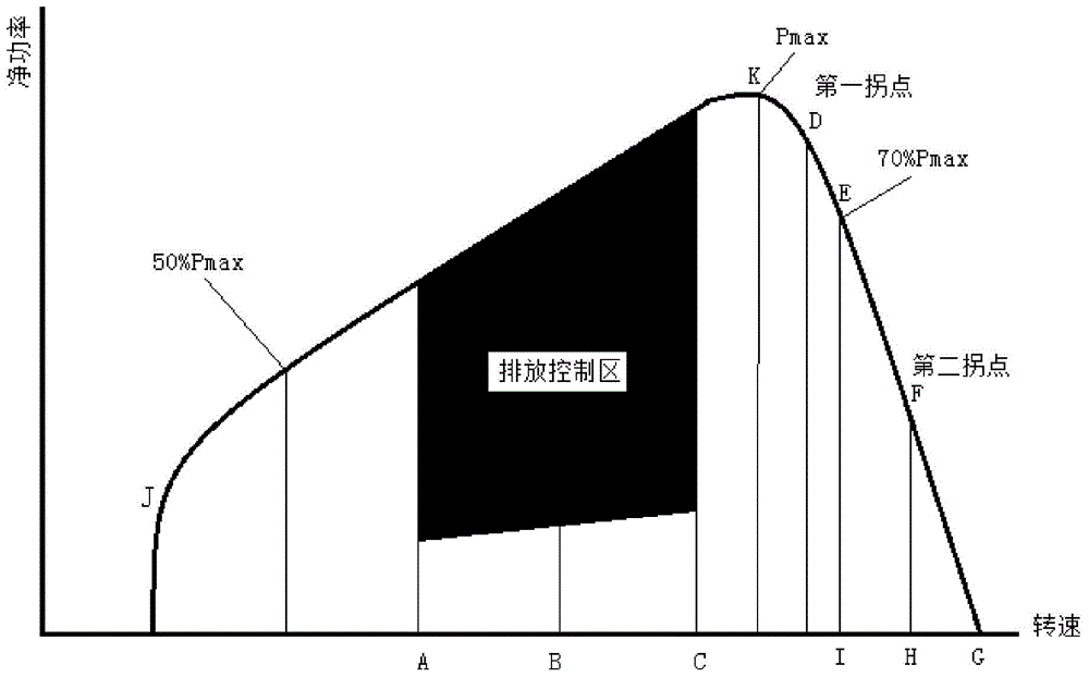
[0014] The existing speed regulation characteristic curve is as follows: figure 1 As shown, among them, the curve JKD is the external characteristic curve, the curve DG is the original speed regulation characteristic curve, and the K point is the rated power point. According to the requirements of the emission regulations GB 17691-2005, the speed at the point 50% Pmax is the maximum net power point K The speed at the point of 50% of the power, the speed of point E is the speed of 70% of the power of the maximum net power point K, the speed of point I is the same as the speed of point E, the speed of point B is 50% of Pmax and the midpoint of point I, point A is the midpoint of point 50% Pmax and point B, and point C is the midpoint of point B and point I. Point J is any point where the speed is less than 50% Pmax, point D is the firs...


PUM


Abstract

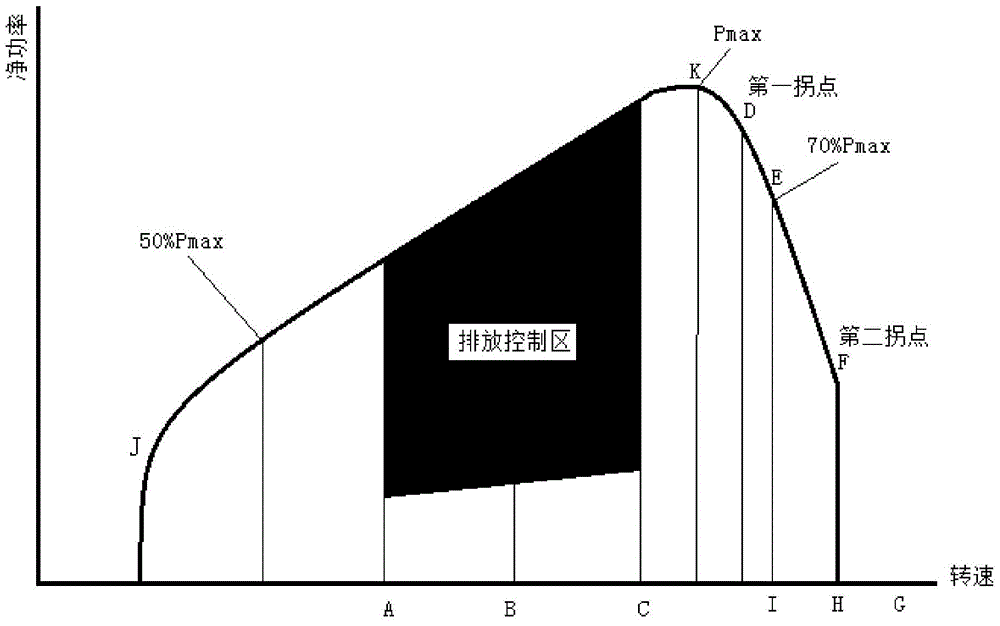
The invention relates to an electric control engine speed adjustment characteristic curve design method. According to the electric control engine speed adjustment characteristic curve design method, a curve of which speed adjustment rate is zero is adopted to replace a curve in an original speed adjustment characteristic curve, wherein the load rate of the curve in the original speed adjustment characteristic curve is low, and an obtained curve is a new speed adjustment characteristic curve; and the curve in the original speed adjustment characteristic curve, of which the load rate is low, is a curve of which the rotation speed is higher than that of a curve corresponding to a second inflection point, wherein the second inflection point is a point located between a point where the power value of the original speed adjustment characteristic curve is 70% of the power value of a rated power point, and a G point. With the electric control engine speed adjustment characteristic curve designed by the method of the invention adopted, an engine will not enter a high-rotation speed and low-torque area below the original speed adjustment characteristic curve under control, and therefore, oil consumption and emission level of the engine can be improved, and the service life of the engine can be prolonged, and dynamic and driving performance of the engine will not be affected.

Description

technical field [0001] The invention relates to the performance and emission control of an electronically controlled engine, in particular to a design method for a speed regulation characteristic curve of an electronically controlled engine, and belongs to the field of electronically controlled engine performance and emission control. Background technique [0002] At present, the speed regulation characteristic curves of existing electronically controlled engines all follow the characteristics of mechanical engines, that is, they are all a straight line with a speed regulation greater than 0%. If the engine runs in the region of low load rate and high speed under the speed regulation characteristic curve, the fuel consumption of the engine will increase significantly, the emission will be high, and the life of engine components will also be reduced. [0003] Therefore, how to design a speed regulation characteristic curve so that the engine does not run in the above-mentione...

Claims


Application Information

Patent Timeline
Patent Type & Authority Applications(China)
IPC IPC(8): F02D11/10
Inventor 舒宇舟孙卫军刘利
Owner DONGFENG CUMMINS ENGINE
Learn More