
Radio fiber connection interface communication library based on FPGA and realization method thereof

A technology of radio optical fiber and connection interface, applied in the field of radio optical fiber connection interface communication library, can solve the problems of not supporting dynamic configuration of radio frequency parameters, not supporting multiple sampling rate switching, and not including flow control, etc., to shorten data transmission delay, Low-latency, easy-to-configure effects

Active Publication Date: 2015-08-05
PEKING UNIV
View PDF5 Cites 7 Cited by
  • Summary
  • Abstract
  • Description
  • Claims
  • Application Information

AI Technical Summary

Problems solved by technology

However, the physical layer delay stipulated in the WiFi 802.11 protocol commonly used in modern civil wireless communications is within 100 microseconds. The current software radio platform cannot meet the requirements of modern wireless communication protocols.
[0007] 2) Does not support dynamic configuration of RF parameters
This is not suitable for many applications that require dynamic configuration of RF parameters, such as cognitive radio
[0008] 3) Does not contain flow control, does not support multiple sampling rate switching
[0009] To sum up, the existing communication library between the software radio platform and the RF front-end cannot support high-speed and low-latency transmission, support flow control at different sampling rates, and support runtime configuration of dynamic RF parameters.

Method used


Image

  • Radio fiber connection interface communication library based on FPGA and realization method thereof
  • Radio fiber connection interface communication library based on FPGA and realization method thereof
  • Radio fiber connection interface communication library based on FPGA and realization method thereof

Examples


Embodiment Construction

[0047] Below in conjunction with accompanying drawing, further describe the present invention through embodiment, but do not limit the scope of the present invention in any way.

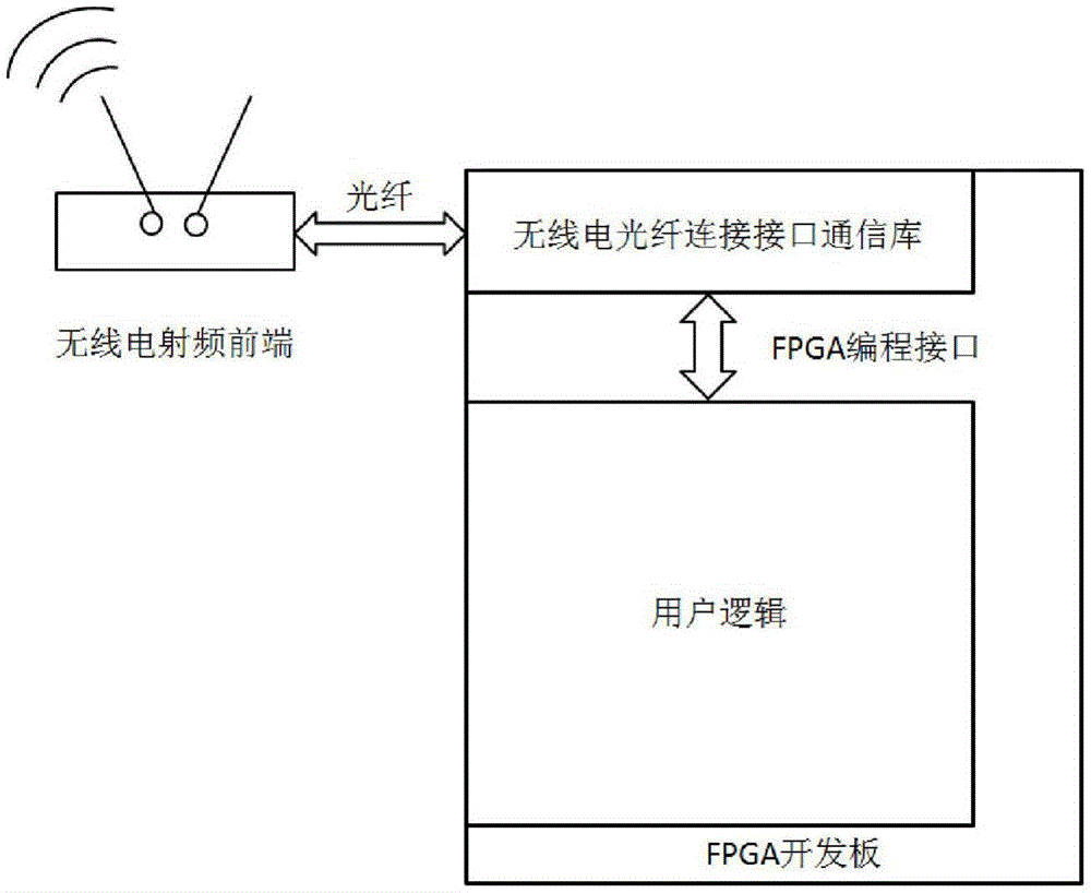
[0048] The present invention provides a radio optical fiber connection interface communication library, including an external interface and an internal module, wherein the external interface includes an FPGA programming interface provided to software radio developers and an optical fiber interface connected with a general radio frequency front end; the radio optical fiber connection interface communication One end of the library is connected to the physical layer of the user-defined radio protocol through the FPGA programming interface, and the other end is connected to the radio frequency front end through the optical fiber interface; the FPGA programming interface includes two sets of signals, which are the data transceiver interface for data transmission and the Parameter configuration interface fo...


PUM


Abstract

The invention discloses a radio fiber connection interface communication library based on a FPGA and a realization method thereof. The radio fiber connection interface communication library makes the FPGA connect with a universal software-defined radio peripheral through an optical fiber interface. The radio fiber connection interface communication library comprises an external interface and an internal module. Through the external interface, the radio fiber connection interface communication library is connected with a wireless local area network reconfigurable physical layer and the radio peripheral. The internal module comprises a peripheral management module, a packager, a fiber interface module, an unpacking device, and a data transmission module. Through using a high-speed low-delay data transmission method, a dynamic radio frequency parameter configuring method, a flow control method based on speed, and a clock domain conversion method based on FIFO and other methods, the radio fiber connection interface communication library and the method solve connection problems of a software-defined radio development platform based on the FPGA and the radio peripheral, and communication library and the method are characterized by high speed, low delay, easy configuration, and support multi-sampling rate and user defined clock domain.

Description

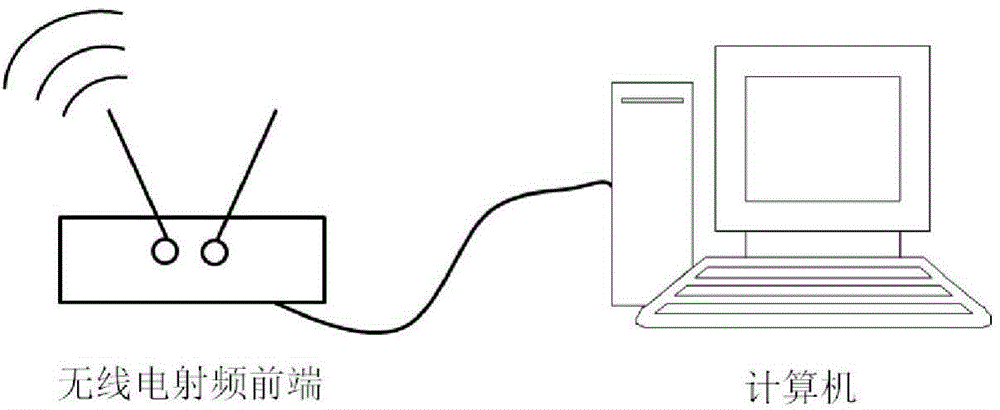
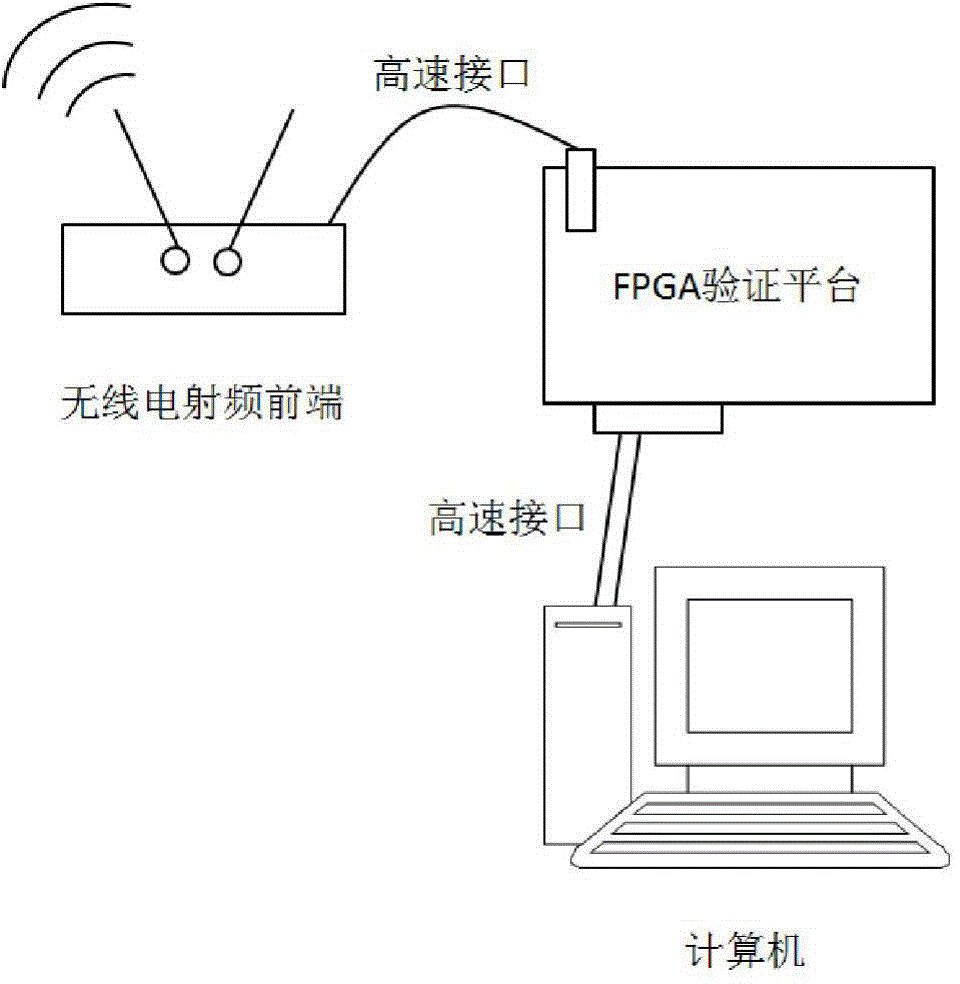
technical field [0001] The invention belongs to the field of radio, relates to an FPGA (Field Programmable Gate Array) and a general software radio radio frequency front end, and in particular relates to a radio optical fiber connection interface communication library and an implementation method for connecting the FPGA and the general software radio front end through optical fibers. Background technique [0002] Software-defined radio is a wireless communication technology that uses a general-purpose configurable radio frequency front-end. The communication protocol is defined by software rather than hardware connections, which is highly flexible and open. Software radio technology accelerates the iteration of wireless communication systems, shortens the product production cycle, and has been used in various communication systems, such as civil mobile communications and military communications. Existing software radio systems are divided into two components (see figure 1 )...

Claims


Application Information

Patent Timeline
IPC IPC(8): H04B10/2575
Inventor 王韬李晓光吴浩洋吕松武
Owner PEKING UNIV
Learn More