
A method for detecting the output accuracy of a resolver for a motor

A resolver and detection method technology, which is applied in the field of detecting the resolver output and angle error to compensate its accuracy, and can solve the problems of vehicle operation safety hazards, increased iron consumption, and difficulty in controlling the accuracy, etc.

Inactive Publication Date: 2017-05-31
MAIERSHITONG ELECTRIC SUZHOU CO LTD
View PDF7 Cites 0 Cited by
  • Summary
  • Abstract
  • Description
  • Claims
  • Application Information

AI Technical Summary

Problems solved by technology

At present, the accuracy of the resolver mainly comes from two aspects. One is the output accuracy of the resolver itself. This accuracy error changes periodically with the rotor position, which makes the rotor position detection error of the permanent magnet motor also change periodically, so that the permanent magnet motor The output current and voltage of the motor change periodically, and the output torque fluctuates periodically, which will generate noise when the vehicle is running. At the same time, the iron consumption of the motor will increase and the efficiency will decrease when the motor is running at high speed, which will reduce the mileage of the vehicle and significantly reduce the driving quality of the vehicle.
Another aspect that affects the accuracy of the resolver is the installation alignment error of the resolver rotor zero position and the motor rotor zero position, which will cause the inherent deviation of the vector angle during the motor vector control operation, making the motor operation deviate from the predetermined optimal curve
[0004] Due to the difficulty in controlling the machining dimension accuracy of the motor stator and rotor and the accuracy of the stator and rotor installation and coordination, when the motor and resolver are installed, the zero position and installation alignment error of the motor rotor is generally at several electrical angles, and it is difficult to ensure consistency
The current solution is: the motor and the resolver are assembled through mechanical adjustment, but this increases the production process, production cost and quality control burden. At the same time, because the installation of the resolver is adjustable and not rigidly connected, it can be adjusted when the vehicle is running. There is a risk of loosening from time to time, which brings safety hazards to vehicle operation

Method used


Image

  • A method for detecting the output accuracy of a resolver for a motor

Examples


Embodiment Construction

[0012] Below in conjunction with the examples, the specific implementation of the present invention will be further described in detail. The following examples are used to illustrate the present invention, but are not intended to limit the scope of the present invention.

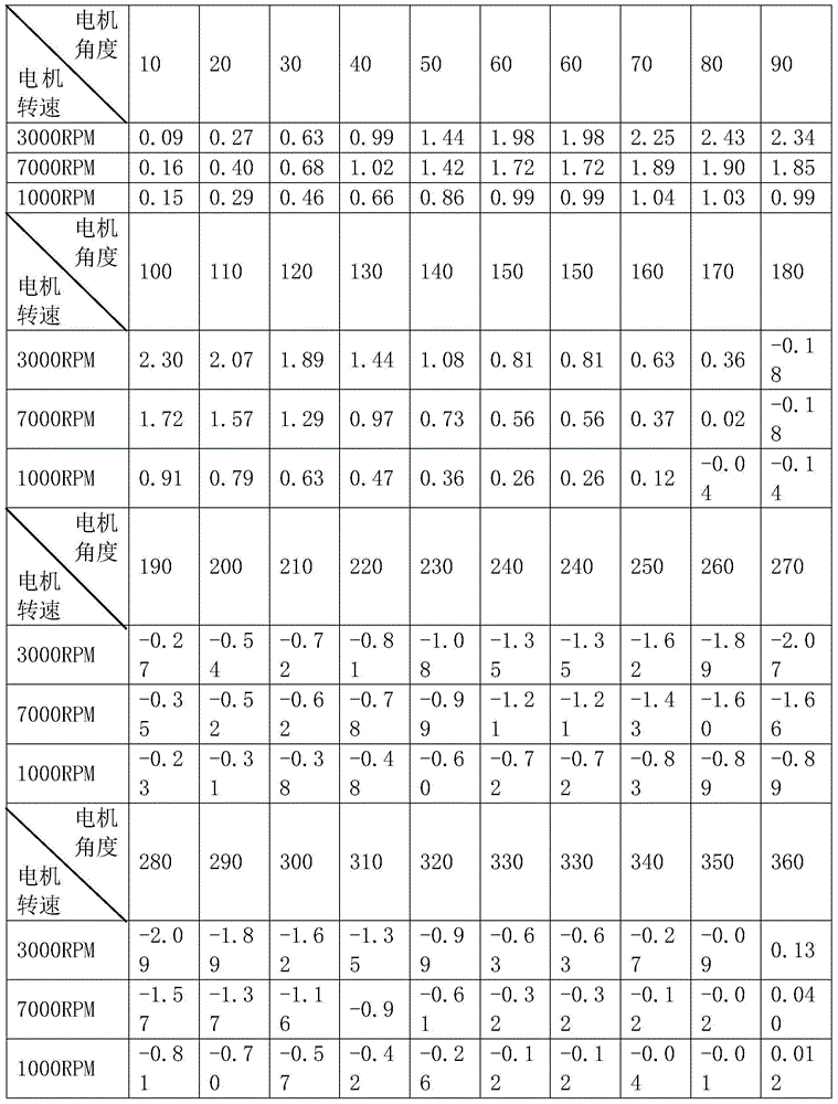
[0013] According to a preferred embodiment of the present invention, a method for detecting the output accuracy of a resolver for a motor, the output end of the resolver is connected to a detection unit, the detection unit includes a first decoding unit and a second decoding unit, and the first decoding unit The bandwidth of the unit is smaller than the bandwidth of the second decoding unit. The first decoding unit is used to detect the output angle of the motor when the motor is running at high speed, and the second decoding unit is used to detect the corresponding output angle of the motor at different speeds of the motor. That is, the high-precision 1. The first decoding unit with low bandwidth can attenu...


PUM


Abstract

The invention relates to a detection method for the output precision of a rotary transformer of a motor. The output end of the rotary transformer is connected with a detection unit. The detection unit includes a first decoding unit and a second decoding unit. The detection method includes the following steps that: an output angle of the motor in high speed operation is detected through utilizing the first decoding unit; corresponding output angles of the motor under different rotation speeds are detected through utilizing the second decoding unit; subtraction processing is performed on each angle outputted by the second decoding unit and the angle outputted by the first decoding unit; and an angle calculation error compensation table can be obtained and is adopted as precision compensation for the rotary transformer. According to the detection method of the invention, the outputs angles of the motor are detected, and angle calculation error compensation is performed, and therefore, the precision of the rotary transformer can be compensated, and the rotor zero position of the rotary transformer and the rotor zero position of the motor are not required to be adjusted through a mechanical mode, and the output torque of the motor can be controlled accurately through the precision compensation of the rotary transformer.

Description

technical field [0001] The invention relates to a rotary transformer for a motor, in particular to a method for detecting output and angle errors of the rotary transformer to compensate for its accuracy. Background technique [0002] Due to its high power density and efficiency, permanent magnet motors are widely used in new energy vehicle drive motors and hybrid vehicle generators. Due to the high reliability and anti-interference ability of resolvers, permanent magnet motors in new energy vehicles The mainstream position sensor. [0003] In order to make the motor run with high quality, the resolver is required to have high precision. At present, the accuracy of the resolver mainly comes from two aspects. One is the output accuracy of the resolver itself. This accuracy error changes periodically with the rotor position, which makes the rotor position detection error of the permanent magnet motor also change periodically, so that the permanent magnet motor The output curr...

Claims


Application Information

Patent Timeline
Patent Type & Authority Patents(China)
IPC IPC(8): G01D18/00
Inventor 王清华李秀涛杨爱喜杨磊姜耕耘
Owner MAIERSHITONG ELECTRIC SUZHOU CO LTD
Learn More