
Self-adaption quasi-PRD control method for photovoltaic grid-connected inverter

A control method and inverter technology, applied in photovoltaic power generation, AC network circuits, single-network parallel feeding arrangements, etc., can solve problems such as poor adaptability to grid impedance changes and poor stability of photovoltaic grid-connected systems

Active Publication Date: 2015-07-29
HARBIN INST OF TECH
View PDF2 Cites 25 Cited by
  • Summary
  • Abstract
  • Description
  • Claims
  • Application Information

AI Technical Summary

Problems solved by technology

[0004] The present invention aims to solve the problems of poor adaptability of existing photovoltaic grid-connected inverters to grid impedance changes and poor stability of photovoltaic grid-connected systems under weak grids

Method used


Image

  • Self-adaption quasi-PRD control method for photovoltaic grid-connected inverter
  • Self-adaption quasi-PRD control method for photovoltaic grid-connected inverter
  • Self-adaption quasi-PRD control method for photovoltaic grid-connected inverter

Examples


specific Embodiment approach 1

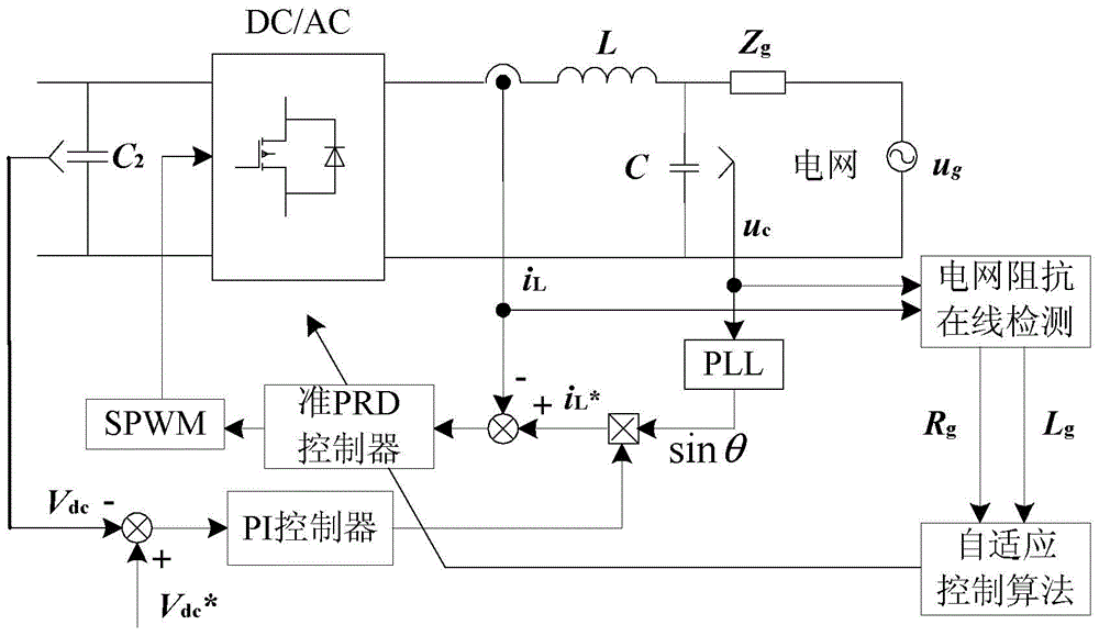
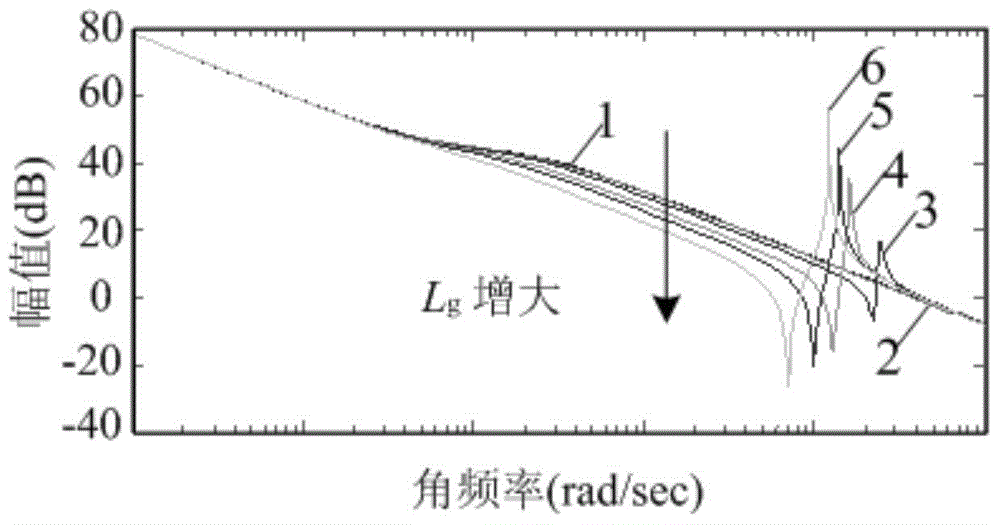
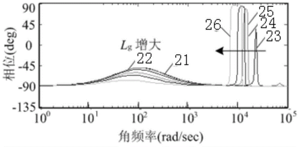
[0044] Specific implementation mode one: refer to Figure 1 to Figure 11 , Figure 18 to Figure 21 Specifically explain this embodiment, the photovoltaic grid-connected inverter adaptive quasi-PRD control method described in this embodiment, it includes the following steps:

[0045] Step 1. Inject a disturbance current of a set frequency into the power grid through the disturbance current injection method through the inverter, and then use the detection element to detect the voltage and current response at the grid-connected point, and then combine the signal processing technology to separate the injected specific subharmonic The modulus value of the wave component, according to which the equivalent grid resistance R is obtained g and grid inductance L g ,

[0046] Step 2. The sinusoidal PWM voltage output by the inverter bridge arm is equivalent to a voltage source, and according to the grid resistance R obtained in step 1 g and grid inductance L g , to establish the tra...

specific Embodiment approach 2

[0065] Specific implementation mode two: refer to Figure 12 to Figure 17 Describe this embodiment in detail. This embodiment is a further description of the self-adaptive quasi-PRD control method for photovoltaic grid-connected inverters described in Embodiment 1. In this embodiment, in step 1, the disturbance current injection method uses Double harmonic current disturbance injection method, that is, the injected disturbance current contains harmonics of two frequencies, the frequencies are respectively 400Hz and 600Hz harmonic current, the location of disturbance injection is a given point of grid-connected current, and the way of disturbance injection For intermittent injection into the grid.

specific Embodiment approach 3

[0066] Specific embodiment 3: This embodiment is to further explain the adaptive quasi-PRD control method of photovoltaic grid-connected inverter described in specific embodiment 1 or 2. In this embodiment, the equivalent grid resistance is obtained according to the modulus R g and grid inductance L g The process is:

[0067] Since there is the following relationship between the impedance of the grid at different frequencies:

[0068] Z 1 2 = R g 2 + ω 1 2 · L g 2 Z ...


PUM


Abstract

The invention relates to a self-adaption quasi-PRD control method for a photovoltaic grid-connected inverter. The self-adaption quasi-PRD control method for the photovoltaic grid-connected inverter relates to the technical field of photovoltaic grid-connected inverter control, and aims to solve the problems that the existing photovoltaic grid-connected inverter has poor adaptability on power grid impedance change, and the stability of a photovoltaic grid-connected system is poor in a weak current grid. The method comprises the following steps of injecting disturbance current with specific frequency into a power grid through a disturbance current injection method; then obtaining a relational expression of current controller parameters and power grid impedance based on the principle of closed loop pole parameter configuration; when the power grid impedance Rg and power grid inductance Lg are changed, realizing self-adapting adjustment on controller parameters Kp, Kr and Kd so as to adapt to the ever-changing power grid impedance, so that the adaptability and the stability of the photovoltaic grid-connected inverter control system are improved. The self-adaption quasi-PRD control method for the photovoltaic grid-connected inverter can be used for controlling the photovoltaic grid-connected inverter.

Description

technical field [0001] The invention relates to an adaptive quasi-PRD control method for a photovoltaic grid-connected inverter. It belongs to the technical field of photovoltaic grid-connected inverter control. Background technique [0002] With the consumption of traditional energy and the maturity of photovoltaic power generation technology, its application scope is also expanding. In order to solve the problem of electricity consumption of scattered users in remote areas and islands, and to make full use of local abundant renewable energy, photovoltaic power generation has begun Promoted and applied in these areas. However, the power grid in the above-mentioned areas is usually the end of the power grid, because the connection between the power generation side and the power generation side has to go through a long transmission line and multi-stage transformer links, the connection becomes weak, and the equivalent line impedance increases. At this time, the power grid pr...

Claims


Application Information

Patent Timeline
IPC IPC(8): H02J3/38H02J3/01
CPCH02J3/01H02J3/383Y02E10/56Y02E40/40
Inventor 王卫刘桂花刘鸿鹏曹小娇吴辉徐殿国
Owner HARBIN INST OF TECH
Learn More