A Debris Flow Impact Force Experimental System

An experimental system and impact force technology, applied in the hydraulic model, etc., can solve the problems of impact application, uncontrollable impact force, lack of data research, etc., to achieve the effect of guaranteed strength and easy observation

Active Publication Date: 2016-08-24
SICHUAN ENG TECHN COLLEGE
View PDF5 Cites 0 Cited by
  • Summary
  • Abstract
  • Description
  • Claims
  • Application Information

AI Technical Summary

Problems solved by technology

However, this experimental device cannot test the impact force of large blocks in debris flow fluid, and the magnitude of the impact force is also uncontrollable. The lack of research on this data affects its application in engineering practice

Method used


Image

  • A Debris Flow Impact Force Experimental System

Examples


Embodiment Construction

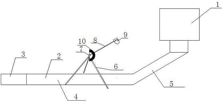
[0017] see figure 1 Shown: the present invention is a mud-rock flow impact test system, comprising a slurry tank 1, a slurry tank 2 and an experimental instrument.

[0018] The above-mentioned slurry tank 1 is arranged upstream of the slurry tank 2, and the slurry in the slurry tank 1 reaches the slurry tank 2 through the flow control valve on the outlet (such as: a circular butterfly valve and other flow control valves, etc.), and at the same time , There is a mud pump in the slurry tank 1, the output flow of the slurry in the slurry tank 1 is controlled by the mud pump, the speed of the slurry entering the slurry tank 2 is controlled through the flow control valve and the mud pump, and the indirect control effect The impact force on the impacted block. The above-mentioned slurry tank 2 is mainly composed of an inclined section 5 and a straight section 4 connected in sequence. The side near the slurry tank 1 is the inclined section 5 of the slurry tank 2, and the side near t...


PUM


Abstract

The invention discloses a mud flow impact force experiment system. The mud flow impact force experiment system comprises a slurry material box, a slurry material tank and an experimental instrument, wherein the slurry material box is arranged on the upstream of the slurry material tank; a collided block is arranged in the slurry material tank; a force sensor is arranged on the collided block; the experimental instrument adopts a simple pendulum structure, and mainly comprises a foot stool, a cross beam and a collision block, wherein the foot stool is used for supporting the cross beam above the slurry material tank; a driving motor is arranged on the cross beam; the output shaft of the driving motor is connected with a swinging rod; a dial scale used for detecting the swinging angle of the swinging rod is arranged on the cross beam; the collision block is connected to the other end of the swinging rod; the experimental instrument is supported above the collided block. According to the mud flow impact force experimental system, the impact force to the collided block caused by a slurry material is controlled by controlling the slurry material output speed of the slurry material box; the impact force of the collision block to the collided block is controlled through a simple pendulum principle of the experimental instrument; further, the interrelation between the impact force of the collision block to the collided block in the slurry material tank and the impact force of the slurry material in the slurry material tank to the collided block is explored.

Description

technical field [0001] The invention relates to a mud-rock flow impact force experiment system. Background technique [0002] In mountainous valleys, disasters caused by special floods that contain a large amount of solid debris such as mud, sand, stones, etc., and have strong impact and destructive effects, caused by heavy rain, a large amount of ice and snow melt water, or rapid surface runoff after the burst of rivers, lakes, and reservoirs. . Debris flow is a common natural disaster phenomenon in mountainous areas. It is a special fluid composed of loose solid materials such as sediment and stones and water. When it erupts, the valley roars, the ground vibrates, and the thick fluid surges and flows down the valley or slope, rushing to the outside of the mountain or the foot of the slope, often causing casualties and property losses in an instant. The physical model test research on the impact force of debris flow is still immature, and there is a lack of data support f...

Claims


Application Information

Patent Timeline
Patent Type & Authority Patents(China)
IPC IPC(8): E02B1/02
CPCE02B1/02
Inventor 吴建文陈源井于云鹏余青霖吉鑫淼
Owner SICHUAN ENG TECHN COLLEGE
Why Eureka
Try Eureka