
Automatic rotating welding device for pipeline

A technology of automatic rotation and welding device, applied in auxiliary devices, welding equipment, auxiliary welding equipment, etc., to achieve the effect of improving work efficiency, ensuring accuracy and good practicability

Inactive Publication Date: 2015-07-29
SHANGHAI INST OF TECH
View PDF9 Cites 12 Cited by
  • Summary
  • Abstract
  • Description
  • Claims
  • Application Information

AI Technical Summary

Problems solved by technology

[0002] When welding circular pipes, the material of the circular pipes is difficult to place. The workpiece is placed flat on the ground and needs to be rotated after a short welding period, or the workpiece stands on the ground and workers During the welding process, the workpiece needs to be rotated, so the accuracy of welding cannot be guaranteed, the welding is more troublesome, it is easy to cause defective products, increase the production cost, and the work efficiency is not high

Method used


Image

  • Automatic rotating welding device for pipeline
  • Automatic rotating welding device for pipeline
  • Automatic rotating welding device for pipeline

Examples


Embodiment approach

[0020] As an embodiment of the present invention, the automatic rotary welding device will be further described below in conjunction with the accompanying drawings.

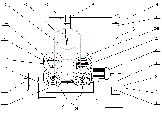
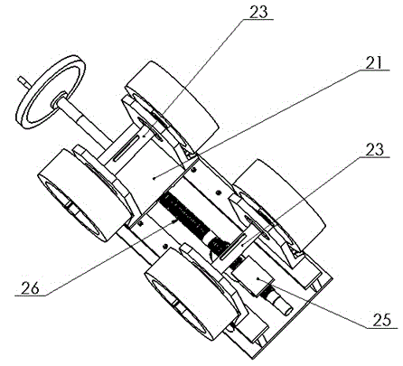
[0021] Such as figure 1 As shown, a pipeline automatic rotary welding device includes a workbench 1 and driving wheels 24 and welding torch brackets assembled at intervals on it. The driving wheels 24 are detachably connected to the driving wheel bracket 22 respectively. The driving wheel 241 and the driven wheel 242 are respectively connected by the driving wheel shaft 23 and installed on the driving wheel bracket 22. The driving wheel bracket 22 is respectively detachably connected to the driving base 2 through the driving slide plate 21 , and the driving slide plate 21 can move horizontally along the driving base 2 . The middle of the driving wheel shaft 23 of the driving wheel 241 is connected with the output end of the speed reducer 28 through a shaft coupling, and the speed reducer 28 is connected with th...


PUM


Abstract

The invention relates to an automatic rotating welding device for a pipeline. The device is that a driving wheel is assembled on a driving wheel bracket, wherein the driving wheel is divided into a driving wheel and a driven wheel which are arranged in parallel and mounted on the driving wheel bracket through driving wheel shafts; the driving wheel bracket is mounted on a driving base through a driving sliding plate; the driving sliding plate can horizontally move along the driving base; a welding gun bracket comprises a lifting vertical column which is vertically arranged, and a transverse cantilever which horizontally extends to be above the driving wheel loading an object; the rear end of the transverse cantilever is detachably connected to the lifting vertical column through a lifting guide sleeve; the transverse cantilever can move up and down; the front end of the transverse cantilever is detachably connected with a welding gun fixing frame of the welding gun through a cantilever arm guide sleeve; the welding gun fixing frame can horizontally move along the cantilever; the welding gun can move in a three-dimensional direction, wherein the three-dimensional direction is namely the guide sliding plate direction, the lifting vertical column direction and the cantilever direction; the welding gun in a certain three-dimensional space can be positioned to any point, so that a weld joint of a welded part can be conveniently positioned, and a stable welding working distance from the welding gun to the weld joint can be kept all the time.

Description

Technical field: [0001] The invention relates to an automatic rotary welding device for pipelines, more precisely, relates to an automatic rotary welding device which is easy to operate and has high production efficiency, and belongs to the field of welding technology. technical background: [0002] When welding circular pipes, it is difficult to place the material of the round pipe. The workpiece is placed flat on the ground and needs to be rotated for a short period of welding, or the workpiece is standing on the ground, and the worker needs to rotate around the workpiece during welding, so the accuracy of welding cannot be guaranteed. Guaranteed, welding is more troublesome, easily causes defective products, increases production cost, and work efficiency is not high. Invention content: [0003] The purpose of the present invention is to provide an automatic rotary welding device for pipelines. The driving wheel drives the workpiece to be welded to rotate at a consta...

Claims


Application Information

Patent Timeline
Patent Type & Authority Applications(China)
IPC IPC(8): B23K37/053B23K37/02
CPCB23K37/053B23K37/0211B23K37/0252B23K37/0538B23K2101/06
Inventor 唐有绮张登博于晓龙朱州罗二宝
Owner SHANGHAI INST OF TECH
Learn More